Allied Telesis AT-RPS8000 User Manual
Page 11
AT-RPS8000 Quick Install Guide
5
Note
Ensure that air flow is unrestricted around the AT-RPS8000 unit.
4.
Attach the provided DC power cord to the DC output connector on the
back panel of the AT-RPS8000 unit, directly behind the pre-installed
AT-PWR8000. (Refer to Figure 4 for the DC output connector.)
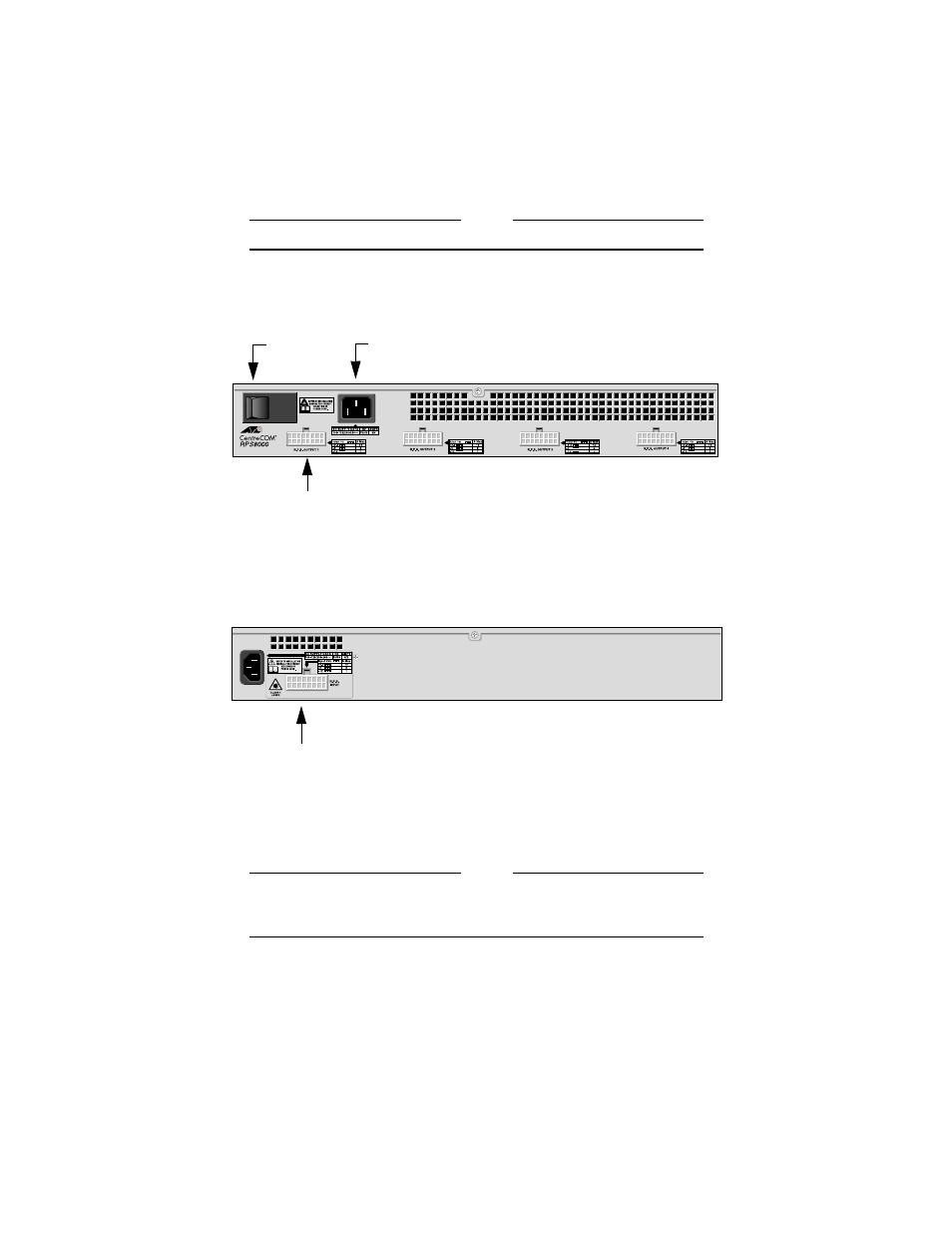
Figure 4 Back Panel of the AT-RPS8000 Unit
5.
Connect the other end of the DC power cord to the R.P.S. Input
connector on the back panel of the Ethernet switch. (Refer to Figure 5
for the R.P.S. Input connector.)
Figure 5 Back Panel of the Ethernet Switch
6.
Plug the AC power cord for the AT-RPS8000 into the AC connector on
the back panel of the unit. (Refer to Figure 4 for the AC connector.)
Note
The AT-RPS8000 unit and Ethernet switches should be connected to
power outlets on separate circuits. This will protect the switches from
a loss of power should a power circuit fail.
7.
Plug the other end of the AC power cord into a wall outlet.
ON/OFF
DC Power Output Connector
AC Power Connector
Switch
R.P.S. Input Connector for the DC Power Cord
- AT-GS908M (54 pages)
- AT-x230-10GP (80 pages)
- AT-GS950/48PS (64 pages)
- AT-GS950/10PS (386 pages)
- AT-GS950/16PS (386 pages)
- AT-GS950/48PS (386 pages)
- AT-9000 Series (258 pages)
- AT-9000 Series (1480 pages)
- IE200 Series (70 pages)
- AT-GS950/8 (52 pages)
- AT-GS950/48 (378 pages)
- AT-GS950/48 (60 pages)
- AT-GS950/48 (410 pages)
- SwitchBlade x8106 (322 pages)
- SwitchBlade x8112 (322 pages)
- SwitchBlade x8106 (240 pages)
- SwitchBlade x8112 (240 pages)
- AT-TQ Series (172 pages)
- AlliedWare Plus Operating System Version 5.4.4C (x310-26FT,x310-26FP,x310-50FT,x310-50FP) (2220 pages)
- FS970M Series (106 pages)
- 8100S Series (140 pages)
- 8100L Series (116 pages)
- x310 Series (116 pages)
- x310 Series (120 pages)
- AT-GS950/24 (366 pages)
- AT-GS950/16 (44 pages)
- AT-GS950/24 (404 pages)
- AT-GS950/16 (404 pages)
- AT-GS950/16 (364 pages)
- AT-GS950/8 (404 pages)
- AT-GS950/8 (364 pages)
- AT-GS950/8 (52 pages)
- AT-8100 Series (330 pages)
- AT-8100 Series (1962 pages)
- AT-FS970M Series (1938 pages)
- AT-FS970M Series (330 pages)
- SwitchBlade x3106 (288 pages)
- SwitchBlade x3112 (294 pages)
- SwitchBlade x3106 (260 pages)
- SwitchBlade x3112 (222 pages)
- AT-S95 CLI (AT-8000GS Series) (397 pages)
- AT-S94 CLI (AT-8000S Series) (402 pages)
- AT-IMC1000T/SFP (23 pages)
- AT-IMC1000TP/SFP (24 pages)
- AT-SBx3106WMB (44 pages)