Fiber optic backbone network configuration, Figure8: at-mr840tf fiber backbone configuration, Workstations (dtes) – Allied Telesis AT-MR840TF User Manual
Page 36
Configurations
16
Fiber Optic Backbone Network Configuration
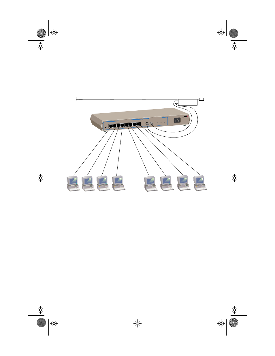
The most straightforward configuration is a hub attached to a fiber optic
(10Base-FL) backbone network. Figure 8 shows a backbone network
configuration using the fiber uplink connector attached to a coaxial Ethernet
cable via a fiber optic transceiver.
Figure 8: AT-MR840TF Fiber Backbone Configuration
Overall, in a backbone network configuration, each workgroup has its own local
network and the backbone is used to link the various workgroups through one
or several hubs. The advantages of a backbone network are twofold:
❑
As long as the backbone network is operating correctly, any problem
within a sub-network does not affect other sub-networks.
❑
Since faults are isolated to a single sub-network, they are easier to
locate.
The IEEE 10Base-FL standard extends a fiber segment length to 2 km. This
applies only to configurations in which one 10Base-FL node connects to another
10Base-FL node.
100 Meters
TP Cable
wired Pin to Pin
10BASE-FL BACKBONE PORT
10BASE-T NET
WORK PORTS
RX
TX
RX
TX
LINK
Workstations (DTEs)
Fiber optic
Transceiver
Coaxial Ethernet
MR840TF_Book Page 16 Tuesday, November 11, 1997 3:46 PM