Table 5: mdi/mdi-x switch position rules, Verifying installation, Make sure that the link ok led of the first con – Allied Telesis AT-MR840TF User Manual
Page 33: After a successful connection, disconnect the a, Establish a connection from a device connected, Once the connection between devices attached to, If all ports test successfully, install the res
AT-MR840TF Hub Installation Guide
13
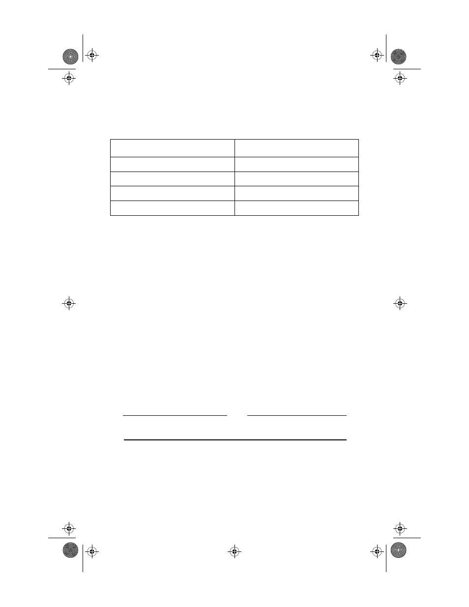
Table 5 lists the MDI/MDI-X switch positions when using straight-through and
crossover cable.
Verifying Installation
1. Make sure that the LINK OK LED of the first connected 10Base-T port is
lit. A steady green LED indicates continuity.
2. After a successful connection, disconnect the active 10Base-T connector
and connect it to the next successive port. Continue this process until all
10Base-T ports have been validated with good network connections.
3. Establish a connection from a device connected to Port 1 to a device
connected to Port 2.
4. Once the connection between devices attached to Ports 1 and 2 has been
successfully established, remove the RJ45 connector from Port 2 and
connect it to each of the subsequent hub’s 10Base-T ports, 3 through 8, to
verify their functions.
5. If all ports test successfully, install the rest of the 10Base-T RJ45
connections and make sure that the LINK LED for each port lights.
Remember, the 10Base-T device on the opposite end of the UTP cable must
be operational.
Note
The LINK OK LED validates the receive pair only. The opposite end
of the UTP segment is responsible for validating the transmit pair.
Table 5: MDI/MDI-X Switch Position Rules
Position
Required Cable
MDI to MDI-X
straight through
MDI-X to MDI
straight through
MDI to MDI
crossover
MDI-X to MDI-X
crossover
MR840TF_Book Page 13 Tuesday, November 11, 1997 3:46 PM