Allied Telesis AT-LMC100ST User Manual
Page 20
Installing the Media Converter
10
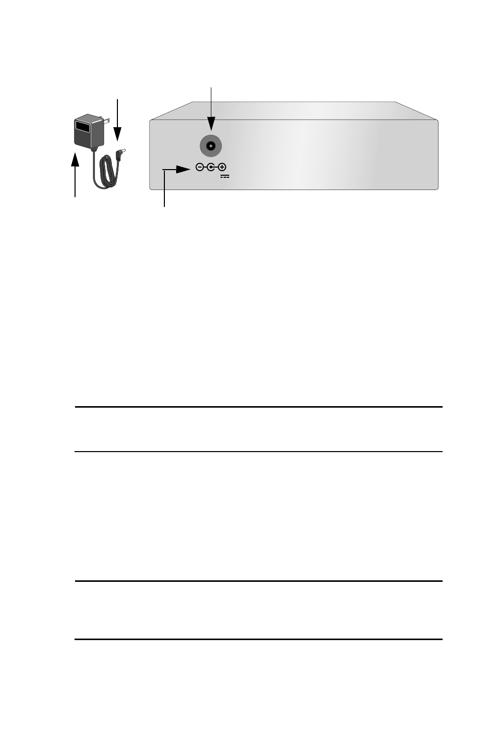
Figure 7 12VDC Connector on Rear Panel
6.
Verify that the PWR LED is green. If the LED is OFF, refer to
“Troubleshooting” on page 13.
7.
Remove the dust cover from the fiber optic connector and connect the
cable to the fiber optic port. Verify that the media converter’s transmitter
port (TX) is connected to the end-node’s receiver port (RX) and that the
media converter’s receiver port (RX) is connected to the end-node’s
transmitter port (TX).
8.
Connect the twisted pair cable to the twisted pair port.
Note
End-nodes connected to the media converter must operate with the
same duplex mode, either both full-duplex or both half-duplex.
9.
Set the MDI/MDI-X switch as follows:
❑
If you are connecting a workstation to the 100Base-TX port, set the
MDI/MDI-X switch to the MDI-X position. MDI-X is the default
position.
❑
If you are connecting a hub or a switch to the 100Base-TX port, set the
MDI/MDI-X switch to the MDI position.
Note
After using the MDI/MDI-X switch to change between the two settings,
you must reset the media converter by powering OFF then powering ON
the unit.
10. Power ON the end-nodes.
The media converter is now ready for use.
12 V D C
Power Plug
DC Receptacle
AC/DC Power Adapter
Back of Media Converter
DC Polarity Symbols