Allied Telesis AR700 Series Router User Manual
Page 11
Installation and Safety Guide
11
1.
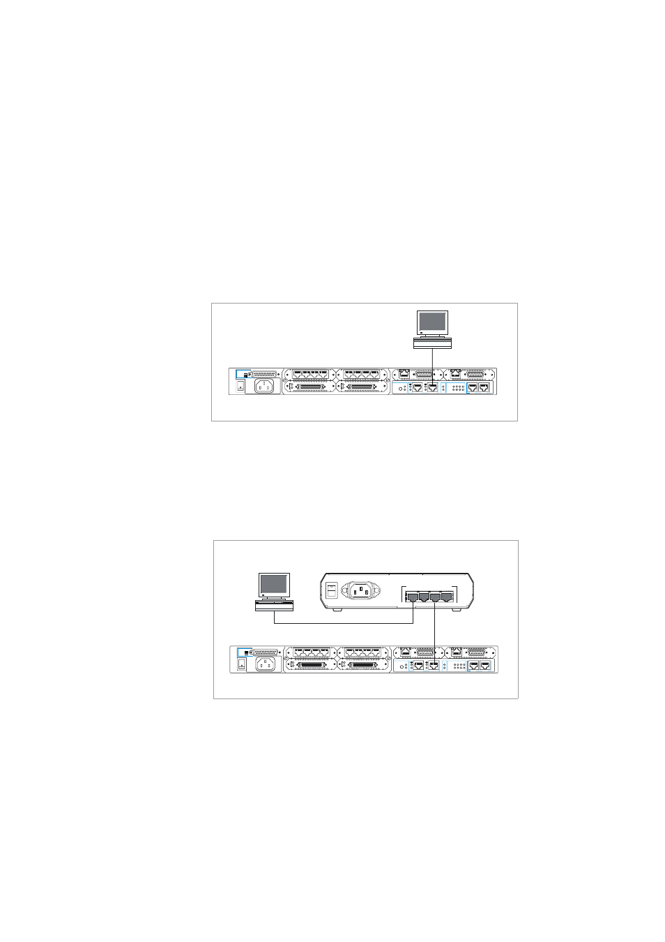
Connect the PC to the router Ethernet port.
The PC can be connected directly, or through your LAN.
To connect the PC directly to the router, use a straight-through Ethernet
cable to connect an Ethernet card on the PC to the router’s Ethernet0 port
(see below). Note the PC’s IP address and mask. (You can browse to the
router through any ETH port, as long as you give that interface an IP
address. These instructions assume you will use Eth0 as the LAN interface.)
To connect via a LAN, use an Ethernet cable to connect the router’s
Ethernet0 port to the device on the LAN (see below). Select the LAN PC
from which you wish to configure the router. The PC should be in the same
subnet as the part of the LAN that contains the router (for example, the
PC could be connected to a hub or Layer 2 switch that is directly
connected to the router’s Ethernet0 port). Note the PC’s IP address and
mask.
2.
Access the CLI on the router.
“Configure the AR725 and AR745 using the CLI”
.
AR700 Series router
PC
Ethernet 0
SYN
Tx
Rx
SYN
Tx
Rx
ASYN
3
0
Data
ETH
Link
Data
ETH
Link
ASYN
3
0
3
1
2
0
AC POWER
100-240
VAC
50-60 Hz
1.0 A
5V/5.5A
12V/1.0A
-12V/0.1A
RPS DC POWER
L/A
L/A
SWAP
NSM 0
HOT
SWAP
IN
100M
ETHERNET 1
ENGINE
ACT
PWR
DAT
RUN
ER
SYS
CLR
SEC
PORT 1
PORT 0
PIC 0
BASE
PIC 1
PIC 0
100M
PIC 1
ETHERNET 0
DISCONNECT POWER BEFORE INSTALLING/REMOVING PIC
PC
3
4
2
1
10BASE-T/100BASE-TX SWITCH PORTS
POWER
ON
OFF
Hub or Layer 2 Switch
AR700 Series router
Ethernet 0
SYN
Tx
Rx
SYN
Tx
Rx
ASYN
3
0
Data
ETH
Link
Data
ETH
Link
ASYN
3
0
3
1
2
0
AC POWER
100-240
VAC
50-60 Hz
1.0 A
5V/5.5A
12V/1.0A
-12V/0.1A
RPS DC POWER
L/A
L/A
SWAP
NSM 0
HOT
SWAP
IN
100M
ETHERNET 1
ENGINE
ACT
PWR
DAT
RUN
ER
SYS
CLR
SEC
PORT 1
PORT 0
PIC 0
BASE
PIC 1
PIC 0
100M
PIC 1
ETHERNET 0
DISCONNECT POWER BEFORE INSTALLING/REMOVING PIC