Connect the dc cable(s), Activate the rps output(s), Check the rps and switch leds – Allied Telesis AT-PWR9000 User Manual
Page 6
6
AT-RPS9000 & AT-PWR9000
C613-04040-01 REV C
7.
Connect the DC cable(s)
On the AT-RPS9000’s rear panel, attach one end of the provided DC cable
to an output connector. Use a connector that is directly behind a bay that
has an installed AT-PWR9000 power unit.
shows the DC
output connectors.
Attach the other end of the DC cable to the RPS input connector on an
AT-9812T or AT-9816GB switch. The RPS input connector is on the switch’s
rear panel.
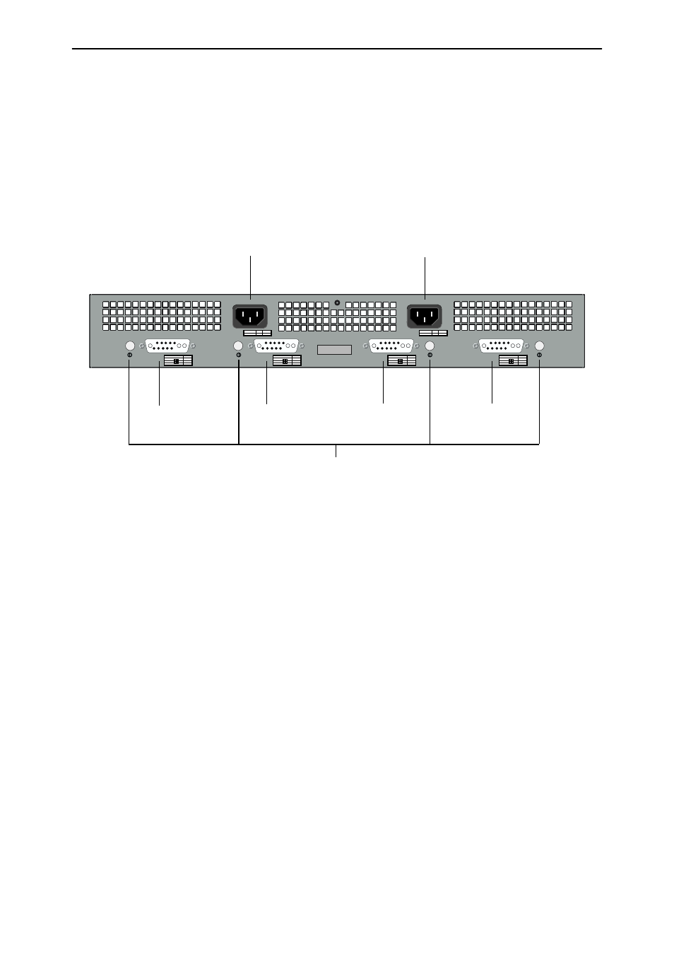
Figure 2: AT-RPS9000 rear panel
8.
Apply power to the AT-PWR9000.
There are two AC inputs on the chassis’s rear panel (see
). Input A feeds the two bays that supply RPS outputs A1 and A2,
while input B feeds the bays that supply outputs B1 and B2.
Use the provided AC power cord(s) to connect the appropriate bays (bays
that have installed AT-PWR9000 units) to a mains power supply.
9.
Activate the RPS output(s).
There are four standby switches on the chassis’s rear panel, one for each
RPS output (see
). Press the standby switch that is closest
to the RPS output you want to activate.
10. Check the RPS and switch LEDs.
RPS and AT-9812T or AT-9816GB switch LEDs indicate the system’s
operational status. See
for more information. If the RPS
does not function as expected, see
AC INPUT A
AC INPUT
100-240V
HZ
50/60
AMPS
5.0-2.5
AC INPUT B
AC INPUT
100-240V
HZ
50/60
AMPS
5.0-2.5
RPS OUPUT A1
RPS OUPUT A2
RPS OUPUT B1
RPS OUPUT B2
OUTPUT VDC
A Max
16
16
0.5
+3.3
+5
+12
OUTPUT VDC
A Max
16
16
0.5
+3.3
+5
+12
OUTPUT VDC
A Max
16
16
0.5
+3.3
+5
+12
OUTPUT VDC
A Max
16
16
0.5
+3.3
+5
+12
AT-RPS9000
AC Input A
(For RPS output A1 & A2)
AC Input B
(For RPS output B1 & B2)
RPS Output A1
RPS Output A2
RPS Output B2
RPS Output B1
Power Switches