Allied Telesis AT-PWR9000 User Manual
Page 5
Quick Install Guide
5
C613-04040-01 REV C
5.
Place the AT-RPS9000 in its operating location.
If installing the RPS on a desktop:
•
Make sure the RPS’s rubber feet are attached.
If installing the RPS in a rack:
•
Remove the rubber feet.
•
Attach the rack-mounting brackets.
•
Mount the RPS in the rack.
For more information on selecting a site, see
.
6.
Install the AT-PWR9000 power unit (if not already installed).
•
In an antistatic environment, remove the AT-PWR9000 from its packing
material. Be sure to observe ESD precautions.
•
On the AT-RPS9000 chassis, choose an empty bay and remove its blank
faceplate by loosening the two Phillips screws until they disengage
from the chassis (see
Keep the faceplate for future use. If you remove a power unit, replace the faceplate to
prevent dust and debris from entering the AT-RPS9000 chassis and to maintain proper
airflow.
The AT-RPS9000 and other AT-PWR9000 units may overheat or be damaged by
dust and debris if bays are left uncovered.
•
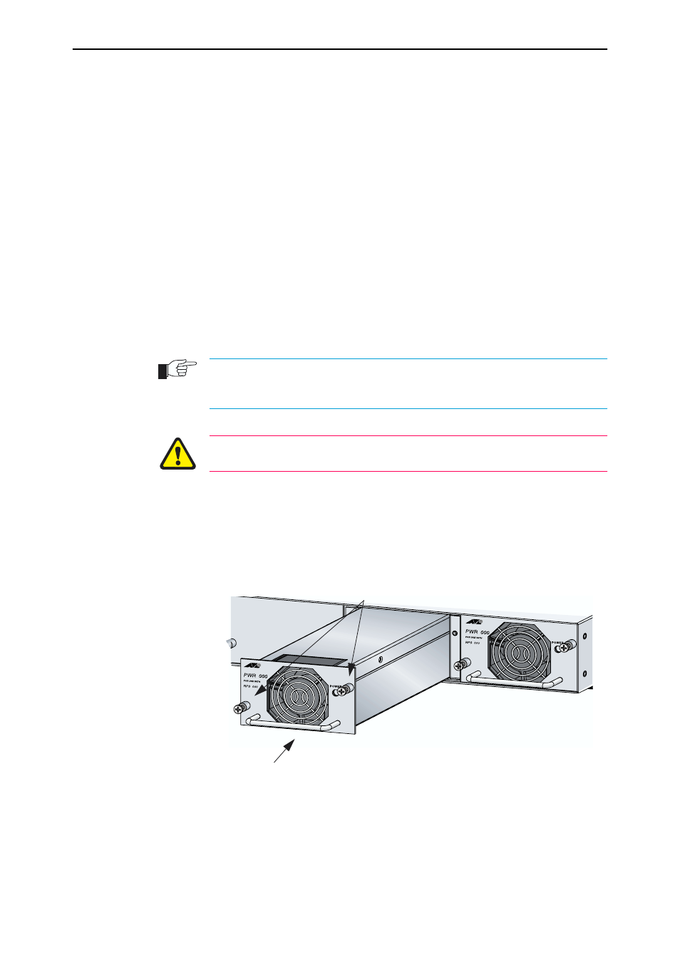
Slowly and carefully slide the power unit into the chassis.
•
Firmly press the power unit home (until its front panel engages or
nearly engages the chassis).
•
Tighten the two Phillips screws on the power unit’s faceplate.
Figure 1: Captive mounting screws on the AT-PWR9000
Handle
Captive Screws
9
9
9
9