Switch ports, Router – Allied Telesis AR400 Series Router User Manual
Page 10
10
AR400 Series Router
613-000313 Rev B
Using the GUI to Configure AR410, AR410S, AR450S
This section describes how to access the GUI via a switch port in VLAN1 on the
AR410, AR410S, AR450S routers, when the PC and the router are in the same
subnet, in order to configure the router. The router’s switch ports all belong to
VLAN1 by default.
The GUI requires a PC and web browser. Supported browsers are Internet Explorer
5.0 or later and Netscape 6.2.2 or later, with JavaScript enabled. If you are using a
toolbar or plug-in on your browser to block pop-ups, disable it while using the GUI.
The GUI displays detailed configuration options and information in pop-up windows.
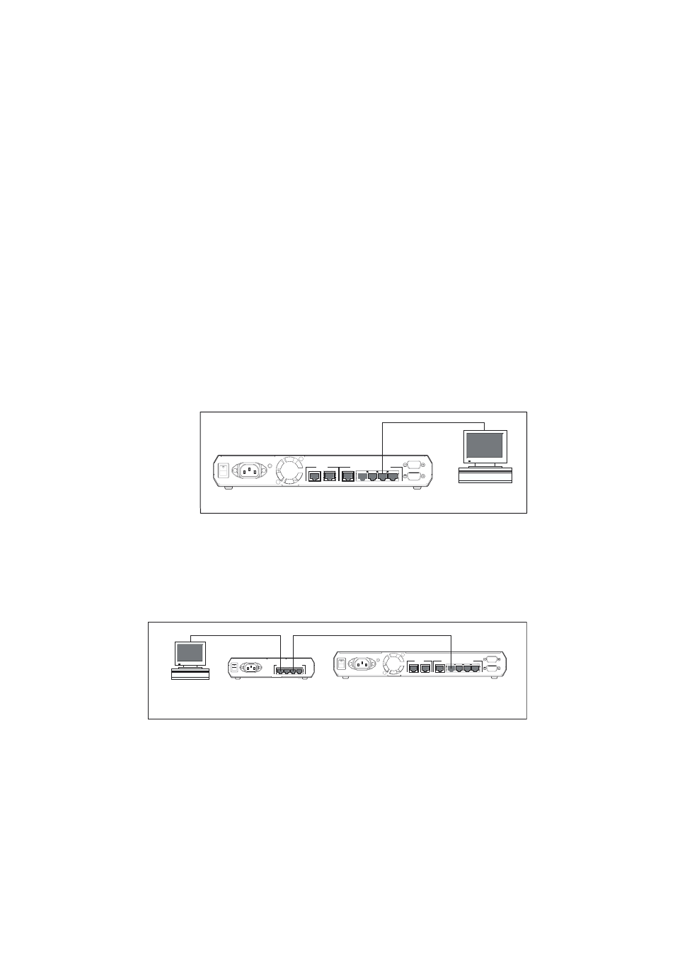
1. Connect the PC to a router switch port.
The PC can be connected either directly or through your LAN.
To connect the PC directly to the router, use a straight-through Ethernet cable
to connect an Ethernet card on the PC to any one of the router’s switch ports.
Note the PC’s IP address and mask.
To connect via a LAN, use an Ethernet cable to connect the router’s switch
port(s) to the device(s) on the LAN. Connect AR410 and AR410S routers
through port 4 and ensure that the PC/hub switch is pressed in. Select the LAN
PC from which you wish to configure the router. The PC should be in the same
subnet as the part of the LAN that contains the router (for example, the PC
could be connected to a hub or Layer 2 switch that is directly connected to one
of the router’s switch ports). Note the PC’s IP address and mask.
PC
router
switch ports
POWER
ON
OFF
RS-232
ETHERNET
3
4
5
0 WAN
1 DMZ
ASYN1
ASYN0 CONSOLE
2
1
10BASE-T/100BASE-TX SWITCH PORTS
straight-through cable
PC
router
switch ports
hub or layer 2
switch
3
4
2
1
10BASE-T/100BASE-TX SWITCH PORTS
POWER
ON
OFF
POWER
ON
OFF
RS-232
ETHERNET
3
4
5
0 WAN
1 DMZ
ASYN1
ASYN0 CONSOLE
2
1
10BASE-T/100BASE-TX SWITCH PORTS