Network topologies, Power workgroup topology, Figure 3. power workgroup topology – Allied Telesis AT-FS708POE User Manual
Page 26: At-fs708/poe fast ethernet switch, Chapter 1: overview 26, Class 1 laser product
Chapter 1: Overview
26
Network Topologies
This section illustrates two network topologies that you can create with the
AT-FS708/POE Fast Ethernet switch: a power workgroup and collapsed
backbone. Both types of topologies are described below.
Power
Workgroup
Topology
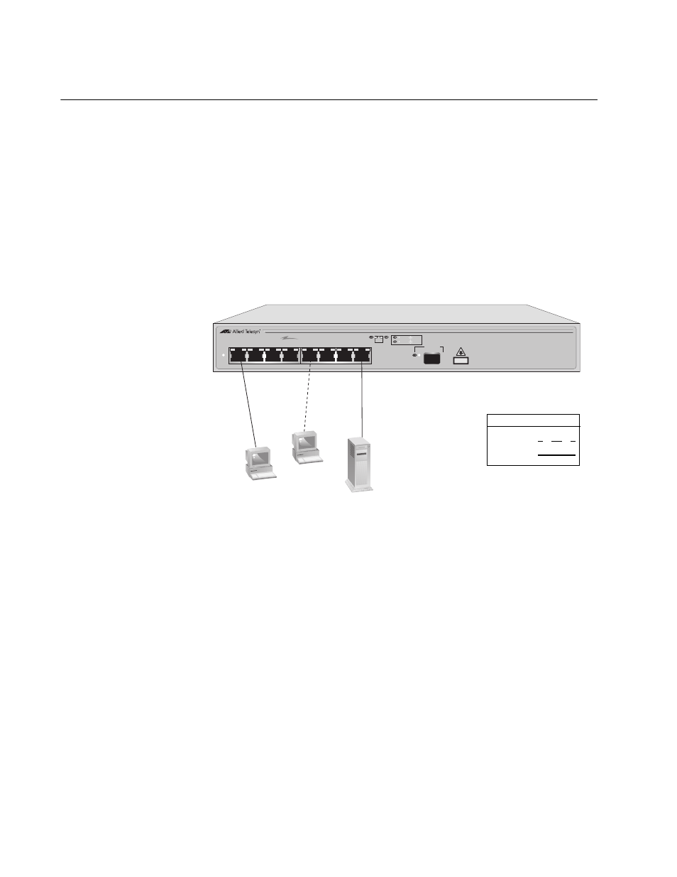
The topology shown in Figure 3 is commonly referred to as a power
workgroup topology. Each workstation or end node is connected directly to
a port on the switch. Each end node has a dedicated data link to the
switch for best performance and reliability. The devices can operate at
10 Mbps or 100 Mbps.
Figure 3. Power Workgroup Topology
AT-FS708/POE
8 port 10/100TX Unmanaged POE Switch w/1 SFP port
POWER
1
2
3
4
5
6
7
8
PoE
SFP
UPLINK PORT
PD ON
PD ERR
LINK
ACT
CLASS 1
LASER PRODUCT
1000Base-X
786
Legend
10 Mbps
100 Mbps
AT-FS708/POE Fast Ethernet Switch
- AT-GS908M (54 pages)
- AT-x230-10GP (80 pages)
- AT-GS950/48PS (64 pages)
- AT-GS950/10PS (386 pages)
- AT-GS950/16PS (386 pages)
- AT-GS950/48PS (386 pages)
- AT-9000 Series (258 pages)
- AT-9000 Series (1480 pages)
- IE200 Series (70 pages)
- AT-GS950/48 (378 pages)
- AT-GS950/48 (60 pages)
- AT-GS950/48 (410 pages)
- AT-GS950/8 (52 pages)
- SwitchBlade x8106 (322 pages)
- SwitchBlade x8112 (322 pages)
- SwitchBlade x8106 (240 pages)
- SwitchBlade x8112 (240 pages)
- AT-TQ Series (172 pages)
- AlliedWare Plus Operating System Version 5.4.4C (x310-26FT,x310-26FP,x310-50FT,x310-50FP) (2220 pages)
- FS970M Series (106 pages)
- 8100L Series (116 pages)
- 8100S Series (140 pages)
- x310 Series (116 pages)
- x310 Series (120 pages)
- AT-GS950/24 (404 pages)
- AT-GS950/24 (366 pages)
- AT-GS950/16 (44 pages)
- AT-GS950/16 (404 pages)
- AT-GS950/16 (364 pages)
- AT-GS950/8 (364 pages)
- AT-GS950/8 (52 pages)
- AT-GS950/8 (404 pages)
- AT-8100 Series (330 pages)
- AT-8100 Series (1962 pages)
- AT-FS970M Series (330 pages)
- AT-FS970M Series (1938 pages)
- SwitchBlade x3106 (288 pages)
- SwitchBlade x3112 (294 pages)
- SwitchBlade x3106 (260 pages)
- SwitchBlade x3112 (222 pages)
- AT-S95 CLI (AT-8000GS Series) (397 pages)
- AT-S94 CLI (AT-8000S Series) (402 pages)
- AT-IMC1000T/SFP (23 pages)
- AT-IMC1000TP/SFP (24 pages)
- AT-SBx3106WMB (44 pages)