Figure 7. alignment guides – Allied Telesis AT-CV1203 User Manual
Page 28
Chapter 2: Installation
28
Note
Empty slots should be kept covered. Retain the slot cover and
reinstall it if you ever remove the line card without replacing it.
2. Remove the Converteon media converter line card or the AT-CV5M02
Management Card from its shipping package.
Store the package in a safe place. You must use the original package
if you need to return the unit to Allied Telesis.
Caution
Be sure to observe all standard electrostatic discharge (ESD)
precautions, such as wearing an antistatic wrist strap, to avoid
damaging the device. Line cards can be damaged by static
electricity.
3. Set the line card’s DIP switches if necessary. For instructions, refer to
the documentation that ships with the line card.
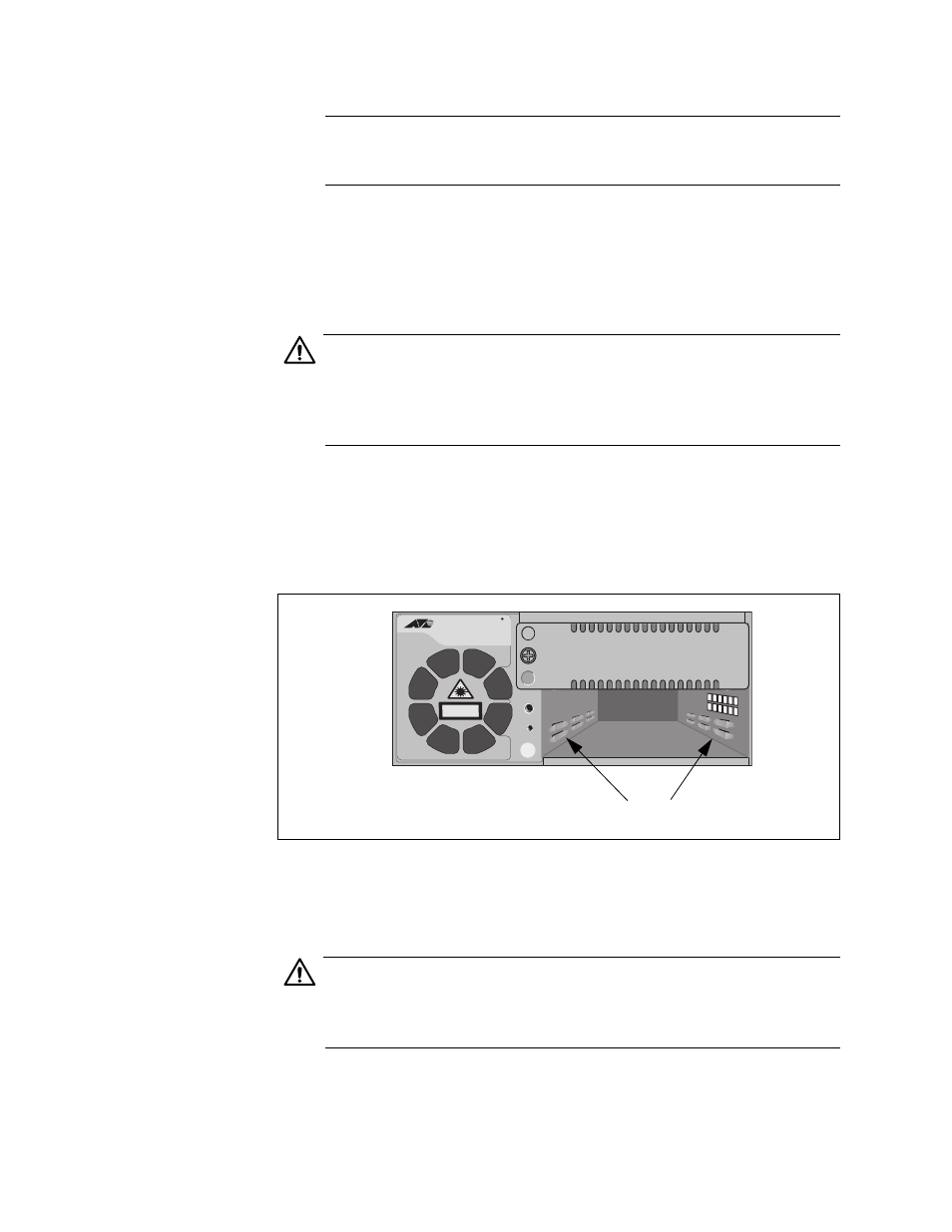
4. Align the edges of the line card with the left and right alignment guides
located inside the slot.
Figure 7. Alignment Guides
5. Slide the line card into the slot, as shown in Figure 8, until the front
panel of the line card is flush with the front of the chassis.
Caution
Do not force the line card into place. If there is resistance, remove
the card, verify that the edges of the card are properly aligned in the
guides in the chassis’ module slot, and reinsert it.
AT-CV1203
CLASS 1
LASER PRODUCT
2
1
Allied Telesis
2
1574
Alignment Guides