Exl series – AFX EXL120WH User Manual
Page 2
EXL SERIES
Line Voltage Xenon Undercabinet Fixture
Models 120, 220, 320, & 420
Interconnectable / Cord or Direct Wire
Page 2 of 2
8060525 R7
Limited Factory Warranty
AFX warrants this fixture is free from defects in materials and workmanship when installed and used under normal operating conditions
for a period of 2 years from date of purchase. This warranty covers all component parts and extends only to replacement of defective fixture
or components; it does not cover failure due to improper installation, misuse, mishandling or damage incurred in transit
.
4.
Link to Fixture Installation
(Skip this step if using Hardwire or Cord to Outlet Installation.)
A. First fixture can be Corded or Hardwired
B. Second fixture must be located within 12” of first fixture.
C. A Maximum of 560 Total Watts can be Linked.
D. Make sure power is off to all fixtures.
E. Connect the Linking cord to the “Out” connector in the first fixture and to the “In” connector of the second fixture. The
connectors only fit one way. Do not force the connections they should snap in easily.
F. Follow directions in Mounting and Lamping Section.
G. Once Mounting and Lamping are completed, energize first fixture.
Note:
Injury to persons and damage to the mounting surface may result if the fixture or mounting hardware is pulled from the mounting
location. To reduce the possibility of such injury, be sure to mount the fixture only on a surface that is mechanically, structurally sound.
5. Mounting
A. Using keyhole slots for mounting the fixture. Position the housing in location intended for mounting. Mark mounting screw location by
using keyhole slots as guides. Remove housing and partially install both #8 x ½” wood screws (provided) in the marked positions. Mount
the housing to desired surface by placing the keyhole slots over mounting screw and shifting housing to one side to secure in position.
Tighten mounting screws.
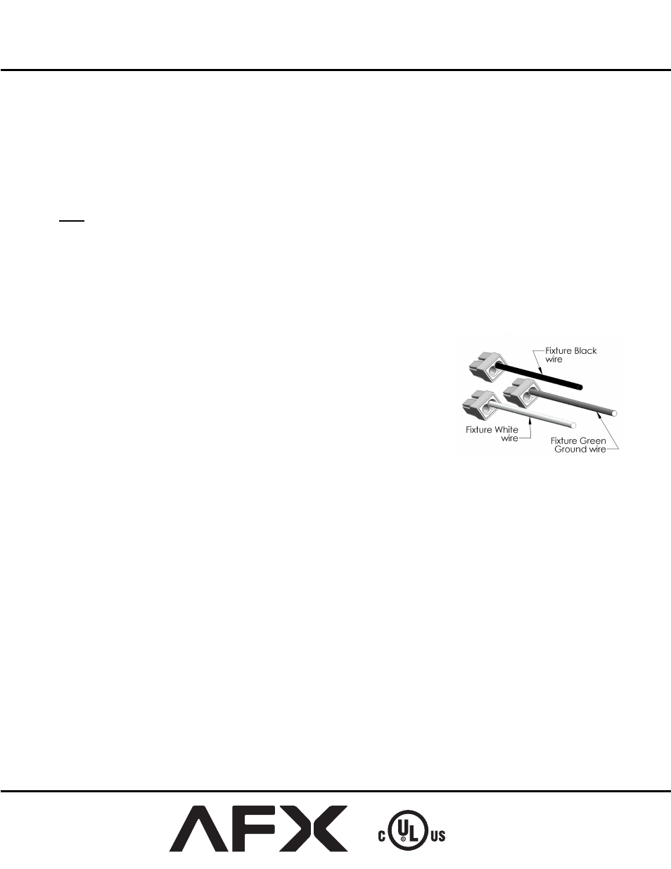
6. Hardwiring Installation Completion
A. Connect the Green ground input supply wire to the fixture Green ground wire. Do this by
inserting it into the open hole in the push-in wire connector (included) that is attached to the
Green ground wire in the fixture.
B. Connect the White input supply wire to the fixture White wire. Do this by inserting it into
the open hole in the push-in wire connector (included) that is attached to the White wire in
the fixture.
C. Connect the Black input supply wire to the fixture Black wire. Do this by inserting it into
the open hole in the push-in wire connector (included) that is attached to the Black wire in
the fixture. Do not mix wires or change polarity.
D. Pull on each wire lead to make sure connections are secure. Make certain no bare wires are
exposed outside of the wire connectors.
E. To close cover- Carefully arrange wires so they do not get pinched and rotate cover against
channel. Secure cover under housing lances.
F. Proceed to Lamping Instructions below.
7. Lamping
DO NOT TOUCH BARE LAMPS WITH BARE HANDS. Oils from your Skin may damage the lamp when it heats up.
A. Remove lamp from box. Hold the lamp by the Pins or with the use of a protective plastic cover (a glove or a plastic bag work well).
B. Install lamps by pushing straight into sockets. Adjust lamp(s) as needed to not touch lens.
C. Replace glass lens by sliding it back into housing until it fully seats within the housing
DO NOT LOOK DIRECTLY AT LIGHTED LAMP.
8. Lamp Removal
A. Allow lamp to cool before handling.
B. Remove the lamp by grasping and pulling straight out from the lamp socket.
C. See the label on the fixture for replacement lamp type information. Maximum 20 watts (BI-PIN base) 120volt Xenon lamp.