AFX ELL9WH User Manual
Ell series, Assembly instructions, Line voltage led undercabinet fixture
ELL SERIES
Line Voltage LED Undercabinet Fixture
Models 9, 12, 18 & 24
Plug-in or Hard Wire, Linkable
Page 1 of 2
8060732 R3
Safety Precautions
Read all safety precautions and installation instructions carefully
before installing or servicing this fixture. Failure to comply with
these instructions could result in potentially fatal electric shock
and/or property damage.
It is recommended that a qualified electrician perform all wiring. This
fixture must be wired in accordance with all national and local
electrical codes.
Do not handle an energized fixture or attempt to energize any fixture
with wet hands or while standing on a wet or damp surface or in
water.
Make sure that the power source conforms to the requirements of the
fixture (See labels on fixture housing). To reduce the risk of electrical
shock, and to assure proper operation, this fixture must be adequately
grounded.
LED lamp and heat-sink are HOT when energized!
Do not touch LED light engine or heat-sink .
12-inch minimum spacing distance from luminaire
required for all objects located under fixture.
This fixture is to be used for general indoor lighting in dry locations
only. Linkable total wattage is 200 Watts.
This fixture is dimmable in the high (II) setting only. The following
dimmers are approved for use to achieve smooth dimming down to
10% of full scale:
Leviton – 6633, 6681, 6621-WWP, 6631-WWP
Lutron – TG-600P, TG-603P
Assembly Instructions
1. Preparation for Installation
A. Disconnect electrical power before installing or servicing any part of
this fixture.
B. Place fixture on a clean flat surface with lens (3) towards you.
C. Remove glass lens (3) by lightly pressing down on both ends while
sliding it directly away from the chassis (1).
D. LED Light Engine (5) is fixed, DO NOT remove or adjust.
E. Determine input power method (Cord, Hardwire or Link) and follow
corresponding directions below.
2. Cord to Outlet Installation
(Skip this step if using Hardwire or Link-to-Fixture Installation)
A. Fixture must be mounted within 5’ of an outlet. Locate the 5’ power
cord included in the box.
B. Connect Cord to fixture by snapping the quick connect end of the cord
to the corresponding connector in the end of the fixture marked “IN”.
The cord will only connect to the “IN” connector so make the right
connector is identified. Do not force the connection, it should snap in easily.
C. Follow the directions for Mounting and Lamping below.
D. Once Mounting and Lamping are completed, plug the cord into the outlet.
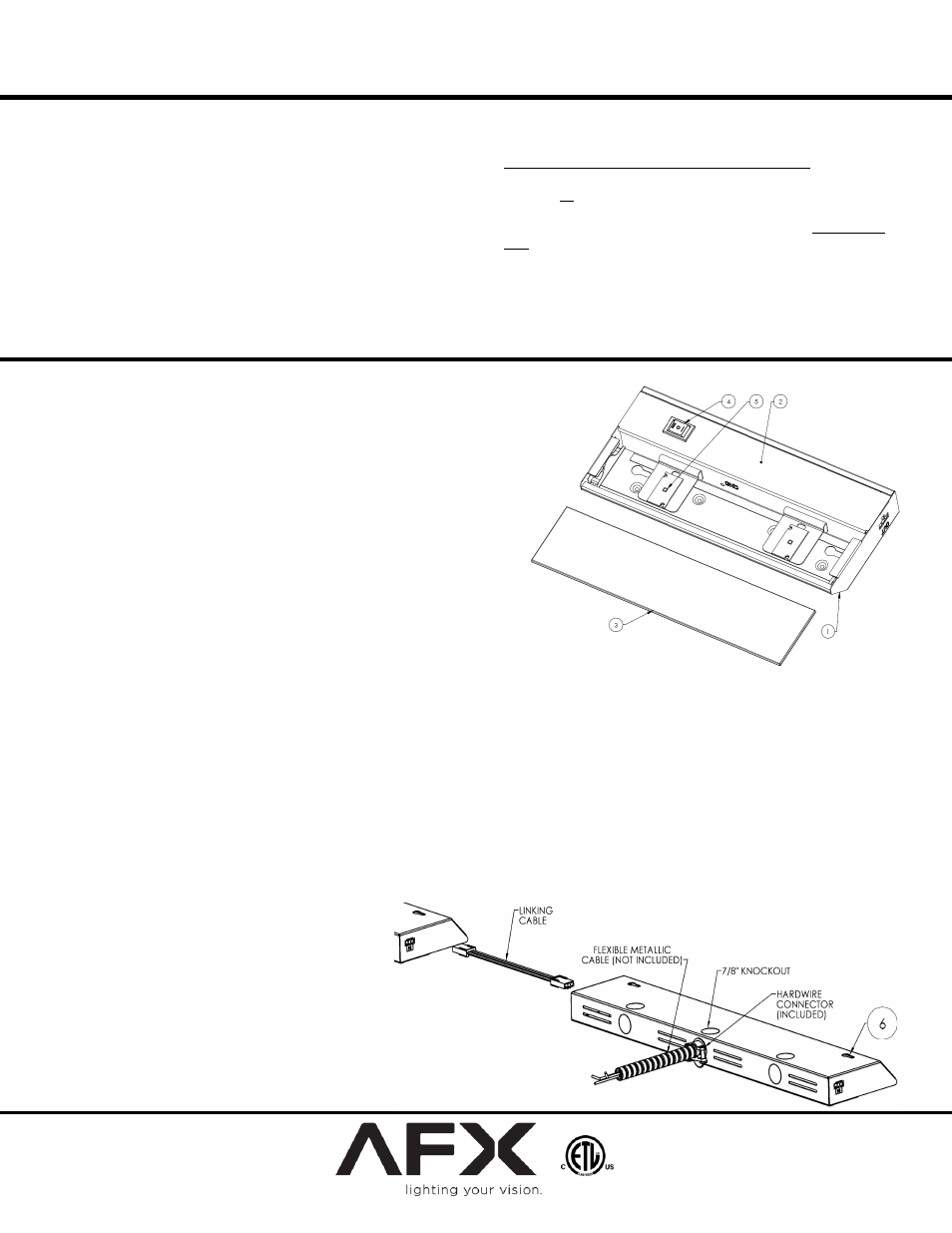
3. Hardwire Installation Preparation
(Skip this step if using Cord to Outlet or Link-to-Fixture Installation to Power Unit)
A. Discard Cord if Hardwire Installation is used.
B. Open cover (2) by squeezing to disengage it from the retaining tabs of the housing. Rotate it 90º.
C. Remove appropriate 7/8” diameter knockout for supply wiring entry.
D. Determine appropriate connector:
i) NM-Romex - A non-metallic push-on connector is included for use.
ii) Flexible conduit (BX) – A push-on connector (shown) is included for use.
E. Insert BX cable (not included) or Romex (not included) through appropriate connector. Feed appropriate supply wires (1 black wire, 1
white wire and 1 ground wire) through open 7/8” hole in the housing and push connector into hole until it snaps in place.
F.
Follow the directions below for Mounting then
proceed to Hardwire Installation Completion.
G. Insert BX cable (not included) or Romex (not
included) through appropriate connector. Feed
appropriate supply wires (1 black wire, 1 white
wire and a ground wire) through open 7/8”
hole in the housing and push connector into
hole until it snaps in place.
www.afxlighting.com