Czp series, Fluorescent pendants – AFX CZP226QSNMV-WHWH User Manual
Page 2
CZP Series
Fluorescent Pendants
Models 218MV / 218SCT / 226MV / 226SCT
Page 2 of 2 8060722 R0
Limited Factory Warranty
AFX Lighting, Inc. warrants this fixture is free from defects in materials and workmanship when installed and used under normal operating conditions
for a period of 3 years from date of purchase. This warranty covers all component parts and extends only to replacement of defective fixture or
components; it does not cover failure due to improper installation, misuse, mishandling or damage incurred in transit.
A. Attach the cord green (or clear) wire to the incoming supply ground wire.
B. Models ending in MV: Using luminaire disconnect adapter provided, insert white supply
wire into the hole across from white ballast lead. Insert black hot supply wire into hole
across from black ballast lead. Do not mix wires.
C. Models ending in SCT: Use wire connectors provided to connect incoming white supply
wire to cord white wire. Connect incoming black supply wire to cord black wire. Do not
mix wires.
D. Pull on each wire to make sure connections are secure. Make certain no bare wires are
exposed outside of wire connectors.
E. Line up the two holes in the canopy (7) with the two screws in the round mounting
bracket. Secure fixture to screws with the two cylindrical thumb nuts (9) provided.
5. Aircraft Cable Adjustments.
A. Adjust the aircraft cables up and down by pressing the “Spring Pin” (8) upward and
holding until the proper cable length is attained. Repeat the same steps to the other cable
assembly. Note: Extra cable length should be looped or tied inside the canopy.
6. Lamp Installation (lamps included on models ending with “SCT”).
A. For models ending in MV, use only 18W/26W (max) fluorescent, quad 4-pin lamps (21). To install, line up lamp pins with
the corresponding holes in the lamp socket (20) and push lamp into place until a click is heard. Repeat for each lamp.
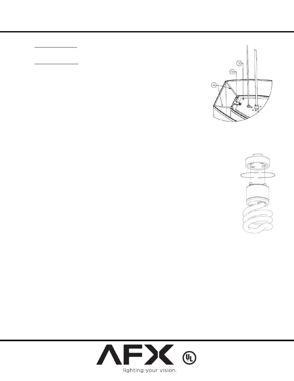
B. Models ending in SCT use a GU24 base lamp (18W/26W max). To install, line up lamp pins with the corresponding holes in
lamp socket and turn clockwise until a click is heard (Fig 4). Repeat for each lamp.
NOTE: BE CAREFUL NOT TO ROTATE PENDANT DURING LAMP
INSTALLATION/REPLACEMENT
7. Inner and Outer Shades Installation (Fig 2 & 3)
A. Install the inner shade assembly (19) to the ballast / wire compartment assembly plate (17). Make sure
the flat head screws (15) are mechanically secure to the top of the plate.
B. Install the outer shade (13) by setting the wireform (14) on top of the perimeter of the inner shade (19)
as shown in Fig 3.
8. Diffuser Installation (Fig 2)
A. Install the plastic diffuser (22) by inserting at an angle and realign to set freely by gravity at the bottom
wireform of the inner shade (19).
*MV model shown with 4-pin CFL’s
FIG 4
*MV model shown with 4-pin CFL’s
FIG 3