Dyp series, Fluorescent pendants – AFX DYP418SNMV User Manual
Page 2
DYP Series
Fluorescent Pendants
Models 418MV / 420SCTD / 618MV/ 620SCTD
Page 2 of 2 8060533 Rev. 3
B. Install and secure the round mounting bracket assembly to the junction box (not provided) in ceiling with the longer screws
(5) provided.
4. Wiring Canopy Cord Assembly to Junction Box.
Caution: Make sure power is off at fuse or circuit breaker box. Check power wires for damage or scrapes. If power supply wires are
within three inches of ballast use wire suitable for at least 90C (194F). Note: Most dwellings built before 1985 have supply wire rated
to 60C. Consult a qualified electrician before installing.
A. Attach (one of the wire in Fig 3) the cord no color wire (13) to the in-coming supply ground wire.
B. Models ending in MV: Using luminaire disconnect provided, insert white supply wire into the hole across from white ballast
lead. Insert black hot supply wire into hole across from black ballast lead. Do not mix wires.
C. Models ending in SCTD: Use wire connectors provided to connect in-coming white supply wire to cord white wire. Connect
in-coming black supply wire to cord black wire. Do not mix wires.
D. Pull on each wire to make sure connections are secure. Make certain no bare wires are exposed outside of wire connectors.
E. Line up the two holes in the canopy (6) with the two screws in the round mounting bracket. Secure fixture to screws with the
two thumb ball nuts (7) provided.
5. Aircraft Cable Adjustments.
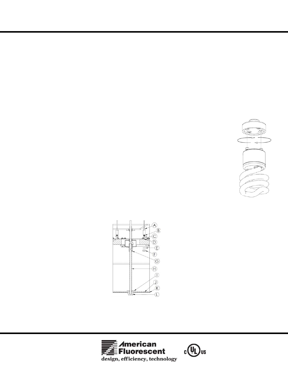
A. Adjust the aircraft cables up and down by pressing the “Spring Pin” (12)(A) Fig 5 downward and
holding until the proper cable length is attained and repeat the same steps to the other two cable
assemblies. Note: Extra cable length should be looped, tied, or cut to minimize lamp shadows.
6. Lamp Installation (Lamps included on models ending with “SCTD”).
A. For models ending in MV, use only 18 watt fluorescent, quad 4-pin lamps (9). To install, line-up lamp
pins with the corresponding holes in the lamp socket and push lamp into place until a click is heard.
Repeat for each lamp.
B. Models ending in SCTD use a GU24 base lamp (20W max.). To install, line up lamp pins with the
corresponding holes in lamp socket and turn clockwise until a click is heard Fig 4. Repeat for each lamp.
NOTE: BE CAREFUL NOT TO ROTATE PENDANT DURING LAMP
INSTALLATION/REPLACEMENT
7. Diffuser Installation
A. Install the shade / stem support assembly (H) to the hub and wire compartment assembly. Make sure the
hex nut (G) mechanically secure at the top and the flat washer (I) is mounted about ½” from the end of
the stem same as shown in Fig 5.
B. Next, install the metal trim ring (K) to the shades wire formed and with the plastic diffuser (J) at the center of the offset
portion of the metal trim ring (K) and at the same time pushing and aligning the hole of the plastic diffuser with the stem and
threading to secure with the finial (L).
Limited Factory Warranty
American Fluorescent Corporation hereby warranty that this fixture is free from defects in materials and workmanship when installed and used under
normal operating conditions for a period of 2 years from date of purchase. This warranty covers all component parts and extends only to replacement
of defective fixture or components; it does not cover failure due to improper installation, misuse, mishandling or damage incurred in transit.
FIG 5
FIG 4