Audiovox Auto Security AA-9300 User Manual
Page 4
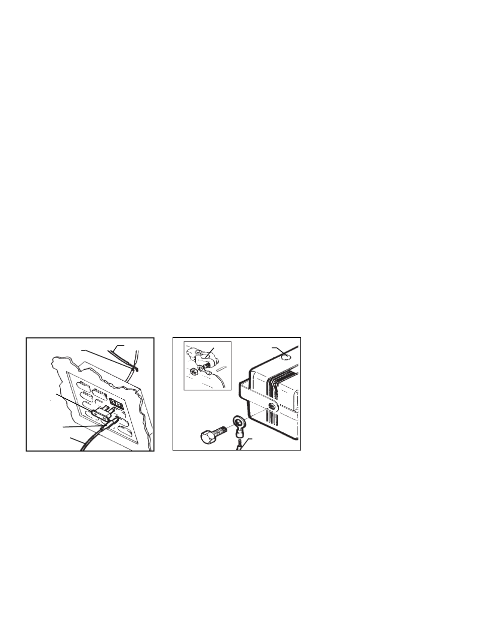
B.
Pass
the
L.E.D.
wires
through
the
hole
from
the
front
of
the
panel,
and
press
the
body
of
the
L.E.D.
into
the
hole
until
fully
seated.
WIRING
THE
SYSTEM
Making
the
connections
to
the
vehicle,
as
described
in
this
wiring
section,
may
be
beyond
the
technical
abilities
of
the
average
consumer.
If
you
have
any
questions
with
the
wiring
procedures,
please
call
a
quali-
fied
automotive
technician,
or
call
the
AUDIOVOX
HOT
LINE
at
1
-
800
-
225
-
6074.
Prior
to
C O U R T E S Y
LIGHT
FUSE
A
SPLICE
INTO
WIRE
AND
WRAP
WITH
E L E C T R I C A L
T A P E
B
FUSE
BOX
FUSE
CLIP
TERMINAL
(NOT
INCLUDED)
RED
WIRE
RED
WIRE
BLACK
WIRE
SIREN
MOD-
U L E
NEGATIVE
TERMINAL
siren
control
module
should
remain
disconnected
during
the
wiring
portion
of
the
installa-
tion.
Leaving
this
disconnected
will
ensure
that
the
keychain
transmitters
are
properly
pro-
grammed
later
in
the
installa-
t i o n .
1.
Routing
The
Wiring
Har-
n e s s
The
DARK
BLUE
wire
must
be
routed
through
the
firewall,
and
into
the
passenger
compart-
ment
of
the
vehicle,
towards
the
dash
L.E.D.
In
most
cases,
the
RED
wire
will
also
be
routed
into
the
passenger
compart-
ment,
to
the
courtesy
light
fuse.
Before
proceeding
with
the
wire
routing,
verify
the
location
of
the
courtesy
light
fuse,
as
a
small
percentage
of
vehicles
locate
this
fuse
in
the
engine
compartment,
and
in
these
cases,
it
will
not
be
necessary
to
route
the
RED
wire
through
the
firewall.
After
confirming
these
compo-
nent
locations,
route
the
DARK
BLUE
and
RED
wires
towards
their
connection
points.
Cau-
tion
should
be
used
when
rout-
ing
wires.
Keep
wires
away
from
all
hot
surfaces,
and
any
mov-
ing
parts
of
the
vehicle
(
radiator
fans,
accelerator
or
brake
pedal
linkage,
etc.
).
When
routing
wires
through
the
firewall,
be
sure
to
pass
the
wires
through
an
existing
rub-
ber
grommet.
Failure
to
do
this
making
any
connections,
a
12
Volt
logic
probe
should
be
used
to
confirm
the
proper
connec-
tion
point.
IMPORTANT
!
The
4
pin
white
connector
on
the
end
of
the
main
harness
that
plugs
into
the
Page 2