S.a.f.e. system theory of operation, System reset, S.a.f.e. parts break down – American Dryer Corp. SL20 User Manual
Page 18
16
113191-2
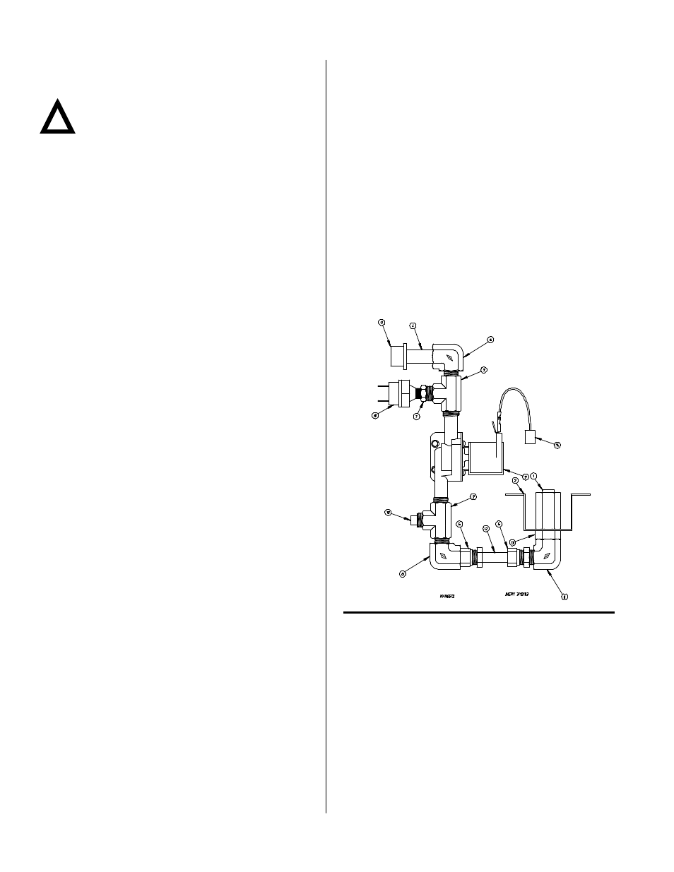
Illus. No. Part No.
Qty.
Description
1
143581
1
3 GPM 3/8” F. P.T. Spray Nozzle
2
318167
1
Nozzle Bracket
3
143220
2
3/8” F.P.T. Brass Tee
4
143242
1
3/8” x 2-1/2” Brass Nipple
5
143208
2
3/8” Comp x 3/8” M.P.T. Brass
Connector
6
143155
3
3/8” Brass Street Elbow
7
143315
1
3/8” M.P.T. x 1/8” Brass Bushing
8
136987
1
Water Jet Pressure Switch
9
165114
1
Solenoid Valve
10
143251
1
3/8” M.P.T. Brass Plug
11
143025
1
3/4-11.5 NH x 3/8” N.P.T. Hose Adapter
12
143099
1
3/8” OD x 0.035 Wall Copper Tubing
13
143303
1
3/8” N.P.T. Brass Lock Nut
14
824081
1
R.C. Network with Terminals
Electrical Requirements
No independent external power source or supply connection
is necessary. The 24 volt power to operate the S.A.F.E. system
is supplied internally from the dryer control.
Warning
Electrical power must be provided to the dryer at all
times. If the main electrical power supply to the
dryer is disconnected, the S.A.F.E. system is
inoperative!!
S.A.F.E. System Theory of Operation __
While the dryer is in an idle state or 20-seconds after the heat
turns off, the Phase 7 control monitors the S.A.F.E. system
probe located in the top of the basket (tumbler) chamber and
records the minimum temperature. If the minimum recorded
S.A.F.E. system probe temperature is greater than 120° F
(48° C) and the control detects a 50° rise in temperature, this
will be the trip point and the S.A.F.E. system routine will
activate.
While a drying cycle is in process and the heat has turned on
at least once, the Phase 7 control monitors the exhaust
temperature transducer. If the drying cycle temperature set
point is set greater than 160° F (71° C) and the control detects
an exhaust temperature rise 25° F greater than set point, this
will be the trip point and the S.A.F.E. system routine will
activate. If set point is below 160° F (71° C) the trip point will
be 185° F (85° C).
Once the S.A.F.E. system routine is activated, the control will
display “S.A.F.E. System Activated” and water will be injected
into the basket (tumbler) chamber. Anytime water is being
injected into the basket (tumbler); the basket (tumbler) drive
will turn the load for 1-second every 15-seconds. This process
will continue for a minimum of 2 minutes. After 2 minutes
has elapsed, the control will check if the temperature
remained above trip point, if so water will remain on. The
control will continue to check if temperature is above trip point
every 30-seconds. If the water has been on for a constant 10
minutes, the water will be turned off regardless of the
temperature and the control will display “S.A.F.E. Was
Activated.” If the temperature has dropped below trip point,
the control will turn off the water prior to 10 minutes.
Disabled S.A.F.E. System
In the event that the S.A.F.E. system is not installed properly
or if there is a malfunction in the system the Phase 7 coin
control will notify the user by displaying the message “S.A.F.E.
DISABLED...” If the “PAUSE” and “LO” keys are
simultaneously pressed, the control will display one of the
following diagnostic messages indicating the fault with the
system. If there is more than one issue with the S.A.F.E.
system, the control will display one message at a time.
S.A.F.E. Diagnostic Messages
Open S.A.F.E. Probe Fault: This message indicates that the
S.A.F.E. probe is either not connected or is damaged.
Shorted S.A.F.E. Probe Fault: This message indicated that
the S.A.F.E. probe is damaged or the wiring is shorted.
Open S.A.F.E. Valve Fault: This indicates that the water valve
is open or that it is not connected to the control.
Shorted S.A.F.E. Valve Fault: This indicates the water valve is
shorted or the wiring to the valve is shorted.
Water Not Connected: This indicates that there is no water
pressure at the water valve. This will occur if water is not
connected to dryer or if there is low water pressure in the
water line coming to the dryer. This could also be a defective
pressure switch or wiring to the pressure switch.
System Reset __________________________
To reset the microprocessor once the control displays
“S.A.F.E. Was Activated,” press and hold the “PAUSE” key for
3-seconds.
S.A.F.E. Parts Break Down _____________
Single Pocket Dryers
Replacement parts can be obtained from your reseller or the
ADC factory. When ordering replacement parts from the
factory, you can FAX your order to ADC at (508) 678-9447 or
telephone your order directly to the ADC Parts Department at
(508) 678-9000. Please specify the dryer model number and
serial number in addition to the description and part number,
so that your order is processed accurately and promptly.
The illustrations on the following pages may not depict your
particular dryer exactly. The illustrations are composite of the
various dryer models. Be sure to check the descriptions of
the parts thoroughly before ordering.
We have tried to make this manual as complete as possible
and hope you will find it useful. ADC reserves the right to
make changes from time to time, without notice or obligation,
in prices, specifications, colors, and material, and to change
or discontinue models.
!