Component testing information, Warning – Amana RS3100007 User Manual
Page 7
Component Testing Information
!
WARNING
To avoid risk of electrical shock, personal injury, or death, disconnect power to washer before servicing, unless
testing requires it.
RS3100007 Rev. 0
7
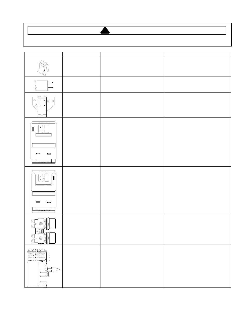
Illustration
Component
Test Procedure
Results
Rocker switch
(Extra Rinse)
Measure resistance of switch
positions:
Closed (ON position)
Open (OFF position)
Continuity
>1
Ω
Infinite
1 M
Ω
Indicator light
Measure voltage at indicator light.
If line voltage is present and light does
not work replace light.
If no voltage is present at indicator light
check wiring.
Signal switch
Measure resistance of the switch
turned to LOUD position.
Nominal 1155
Ω
±
5%
L1
L2
2
1
Temperature switch
Disconnect wires from component to
properly measure the resistance of the
component.
Place switch in the following positions
and measure across the terminals
below:
Hot / Cold
L1-2
Warm / Warm
L1-1, L1-2, L2-2
L2-1, L2-L1, 1-2
Warm / Cold
L1-1, L1-2, 1-2
Cold / Cold
L1-1
>1
Ω
>1
Ω
>1
Ω
>1
Ω
L1
L2
2
C
Speed switch
Disconnect wires from component to
properly measure the resistance of the
component.
Place switch in the following positions
and measure across the terminals
shown below:
Reg / Fast
L1-C, L2-C
Reg /Slow
L1-C, L2-2
Gentle / Fast
L1-2, L2-C
Gentle / Slow
L1-2, L2-2
>1
Ω
>1
Ω
>1
Ω
>1
Ω
Mixing valve
Measure resistance of terminals on
each valve.
Resistance across each valve.
Approximately 1000
Ω
±
10%
Timer
Verify input and output voltage is
present.
Refer to specific model Technical Sheet
for timing sequence chart and functional
description of the component.