Appendix g - unit connectors, The rs-232 serial connectors, Pinout information – Axis Communications 2460 User Manual
Page 64: Unit connectors
Unit Connectors
AXIS 2460 User’s Manual
64
Appendix G - Unit Connectors
This section provides an overview of the product’s connectors, namely:
•2 x RS-232 Serial Connectors
•1 x I/O Terminal Block Connector
•4 x BNC Video Inputs
•4 x BNC Video Outputs
•1 x Ethernet network connector (RJ-45)
The RS-232 Serial Connectors
In the absence of a local network connection, the 9-pin D-sub connector COM2 provides a
dedicated physical interface for connecting a modem or computer to the AXIS 2460. This
RS-232 interface supports modem speeds of up to 115kbps and effectively allows the AXIS
2460 to operate as a standalone unit, independent of any computer network. The
maximum cable length for RS-232 should not exceed 15 meters (50 feet).
If a local network connection is unavailable at the point of installation, you can simply
connect your PC to this connector using the supplied Null Modem Cable. This will allow
you to complete the initial configuration of your product.
Both serial connectors (COM1 and COM2) can be used for running Generic TCP/IP or
Generic HTTP applications. The pinout for COM1 is different to that of COM2.
Note:
Axis Communications maintains a list of all supported modems. Please visit our Website at
www.axis.com for this and other late information on our products.
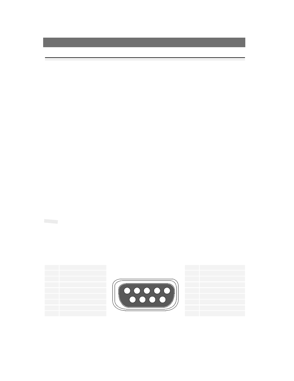
Pinout Information
A diagram of the RS-232 connectors, complete with pinout information, is shown below.
COM1 Pinout
COM2 Pinout
Pin
Function
Pin
Function
1
Not connected
1
CD (Carrier Detect)
2
RXD (Receive Data)
2
RXD (Receive Data)
3
TXD (Transmit Data)
3
TXD (Transmit Data)
4
RTS (Return To Send)
4
DTR (Data Terminal Ready)
5
GND (Ground)
5
GND (Ground)
6
DSR (Data Signal Ready)
6
DSR (Data Signal Ready)
7
RTS (Request To Send)
7
RTS (Request To Send)
8
Not connected
8
CTS (Clear To Send)
9
Not connected
9
RI (Ring Indicator)
1
9
2
3
4
5
8
7
6