Asus dsbf-de series, Dsbf-de series lpc debug card connector lpc1 – Asus Motherboard DSBF-DE/SAS User Manual
Page 63
ASUS DSBF-DE Series
-
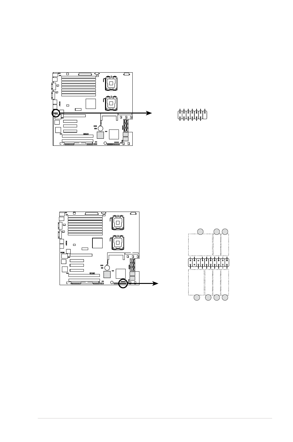
15. LPC debug card connector (14-1 pin LPC1)
This is a low pin count interface used to plug in the LPC debug card.
®
DSBF-DE Series LPC debug card connector
LPC1
+3.3V
PIN1
+3.3
V
+3.3V
GN
D
GND
LPC_LAD
2
LPC_LAD3
LPC_LAD
0
LPC_LAD1
PL
TRST
LFRAME_N
CL
K
GND
16. Auxiliary panel connector (20-pin AUX_PANEL1)
This connector is for additional front panel features including front panel SMB,
locator LED and switch, chassis intrusion, and LAN LEDs.
1. Front panel SMB (6-1 pin FPSMB)
These leads connect the front panel SMBus cable.
2. LAN activity LED (2-pin LAN1_LED, LAN2_LED)
These leads are for Gigabit LAN activity LEDs on the front panel.
3 Chassis intrusion (4-1 pin CHASSIS)
These leads are for the intrusion detection feature for chassis with
intrusion sensor or microswitch. When you remove any chassis
component, the sensor triggers and sends a high-level signal to these
leads to record a chassis intrusion event.
4. Locator LED (6-pin LOCATOR)
These leads are for the locator switch and LED on the front panel.
®
DSBF-DE Series Auxiliary panel connector
AUX_PANEL1
I2C_4_D
AT
A#
LOC
AT
ORLED1+
+5VSB
LOC
AT
ORLED1-
LAN1_LINK
LOC
AT
ORBTN
#
LAN1_AC
T
GN
D
+5VS
B
I2C_4_CLK#
GND
GN
D
LAN2_AC
T
LOC
AT
ORLED2-
LAN2_LINK
LOC
AT
ORLED2+
CASEOPEN
PIN1
NC
1
2
2
5
4
3
4