2. j-bolt template assembly, 3. positioning the j-bolt in concrete, Figure 7-2 – Campbell Scientific UT10 10 foot Tower w/ Grounding Kit and Hinged Base User Manual
Page 19: N figure
UT10 Weather Station
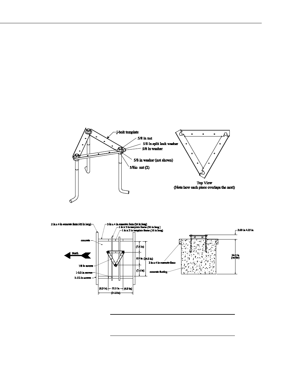
3. Construct a concrete form shown in FIGURE 7-3 out of 2 inch x 4 inch
lumber 24 inch square (inside dimensions). Construct the 1 inch x 2 inch
template frame and set it aside. Center the form over the hole and drive a
stake centered along the outside edge of each side. Level the form by
driving nails through the stakes and into the form while holding the form
level.
4.
Position the J-bolt template as shown in FIGURE 7-3. The top of each
bolt will be 3.00 inch ±0.25 inch above the level of the form. Level the
tops of the J-bolts in all directions using a small level and secure the J-bolt
template to the template frame with 7/8 inch screws where holes in the
template overlap the wooden frame.
5. Fill the hole and form with concrete. Screed the concrete level with the
top of the form as shown in FIGURE 7-3. Smooth the concrete around the
three J-bolts and allow the concrete to harden.
FIGURE 7-2. J-bolt Template Assembly
FIGURE 7-3. Positioning the J-bolt in concrete.
It is common for air to be trapped behind the knee portion of
a J-bolt. Use a stick or rod to stir and tamp around each J-
bolt to ensure proper anchoring.
CAUTION
9