2 programming, 1 input range, Programming – Campbell Scientific LP02 Hukseflux Pyranometer User Manual
Page 17: Input range
LP02 Pyranometer
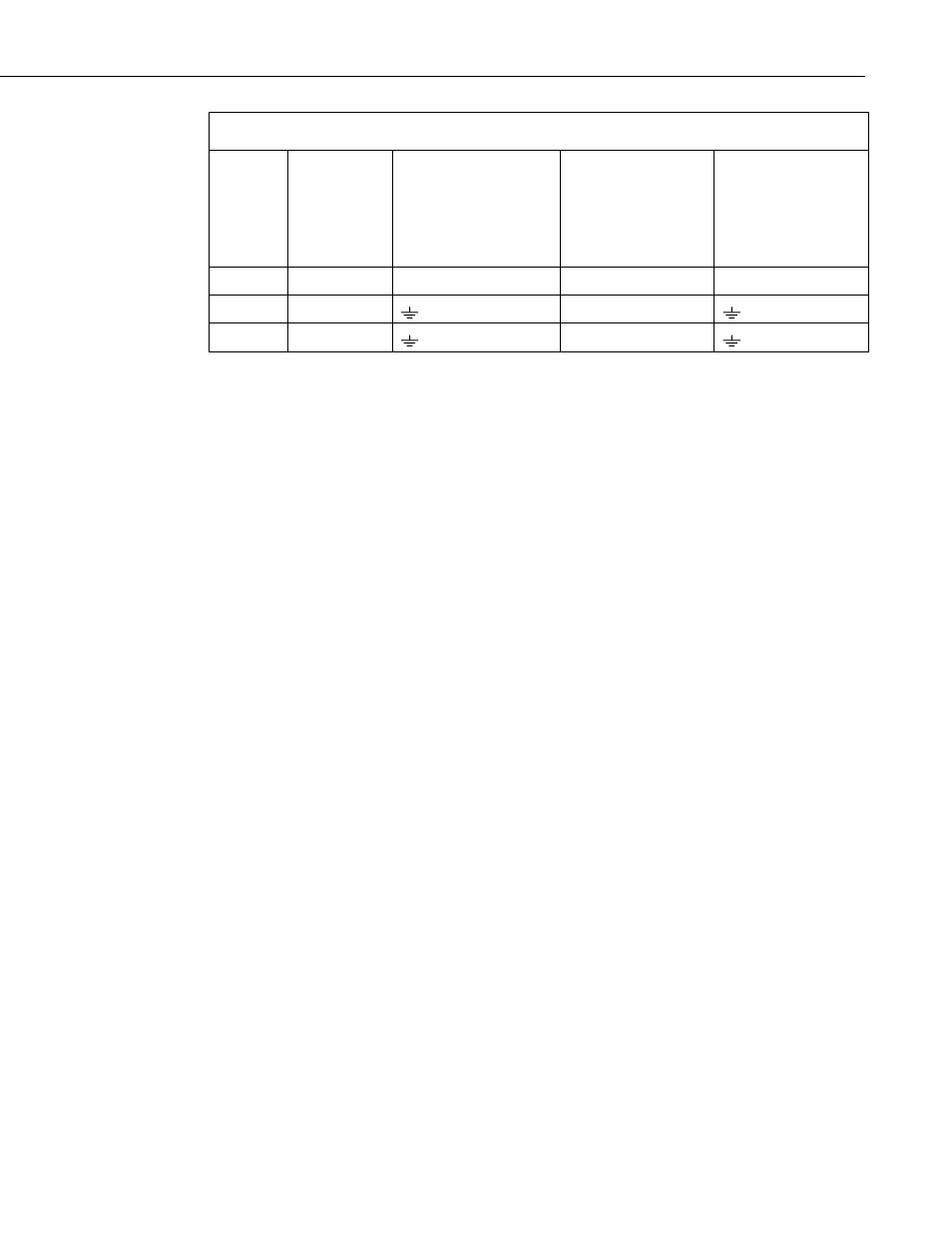
TABLE 7-2. Single-Ended Connections to Campbell Scientific Dataloggers
Color
Description
CR9000(X)
CR5000
CR3000
CR1000
CR800
CR850
CR510
CR500
CR10(X)
21X
CR7
CR23X
White
Signal (+)
Single-Ended Analog
Single-Ended Analog Single-Ended Analog
Green
Signal (–)
AG
Clear
Shield
G
7.2 Programming
This section is for users who write their own datalogger programs. A
datalogger program to measure this sensor can be created using Short Cut.
You do not need to read this section to use Short Cut.
Solar radiation can be reported as an average flux density (W m
–2
) or daily total
flux density (MJ m
–2
). The appropriate multipliers are listed in TABLE 7-3.
Programming examples are given for both average and daily total solar
radiation.
The LP02 outputs a low level voltage ranging from 0 to a maximum of up to
35 mV, in natural light, depending on the calibration factor and radiation level.
A differential voltage measurement is recommended because it has better noise
rejection than a single-ended measurement. If a differential channel is not
available, a single-ended measurement can be used. The acceptability of a
single-ended measurement can be determined by simply comparing the results
of single-ended and differential measurements made under the same
conditions.
7.2.1 Input Range
The output voltage of the LP02 is usually between 10 and 35 mV per
1000 W m
–2
. When estimating the maximum likely value of sensor output, a
maximum value of solar radiation of 1100 W m
–2
can be used for field
measurements on a horizontal surface.
Select the input range as follows:
1. Estimate the maximum expected input voltage by multiplying the
maximum expected irradiance (W m
–2
) by the calibration factor (µV/
W m
–2
). Divide the answer by 1000 to give the maximum in millivolt
units.
2. Select the smallest input range which is greater than the maximum
expected input voltage. Normally the 50 mV range for the CR3000,
CR9000(X), CR5000, CR7, CR23X, 21X, and the 25 mV or 250 mV
range for the CR800, CR850, CR1000, CR10X, CR510, and CR500 will
be suitable. The exact range will depend on the sensitivity of your
11