Operation, 1 wiring, Wiring – Campbell Scientific LP02 Hukseflux Pyranometer User Manual
Page 16: 1. lp02 schematic
LP02 Pyranometer
7. Operation
7.1 Wiring
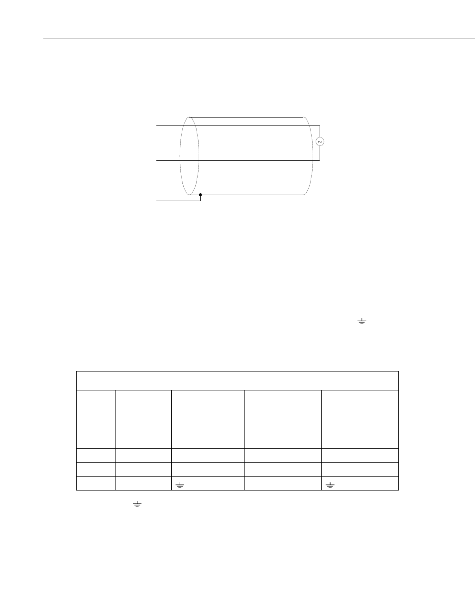
A schematic diagram of the LP02 is shown in FIGURE 7-1.
White
Green
Clear
FIGURE 7-1. LP02 Schematic
When Short Cut is used to create the datalogger program, the sensor should be
wired to the channels shown in the wiring diagram created by Short Cut.
A differential voltage measurement is recommended because it has better noise
rejection than a single-ended measurement. If a differential channel is not
available, a single-ended measurement can be used.
Connections to Campbell Scientific dataloggers for a differential measurement
are given in TABLE 7-1. A user-supplied jumper wire should be connected
between the low side of the differential input and ground (AG or
) to keep
the signal in common mode range.
Connections to Campbell Scientific dataloggers for a single-ended
measurement are given in TABLE 7-2.
TABLE 7-1. Differential Connections to Campbell Scientific Dataloggers
Color
Description
CR9000(X)
CR5000
CR3000
CR1000
CR800
CR850
CR510
CR500
CR10(X)
21X
CR7
CR23X
White
Signal (+)
DIFF Analog High
DIFF Analog High
DIFF Analog High
Green
Signal (–)
*DIFF Analog Low *DIFF Analog Low
*DIFF Analog Low
Clear
Shield
G
* Jumper to AG or
with user supplied wire.
10