1 cs700 connections – Campbell Scientific CS700 Tipping Bucket Rain Gage and CS700H Heated Rain Gage User Manual
Page 13
CS700 and CS700H Rain Gage
4.1 CS700 Connections
The CS700 is typically wired to a datalogger’s pulse channel (see Table 4-1).
TABLE 4-1. CS700 Wiring for Pulse Channel Input
Color
Description
CR800,
CR850
CR1000
CR3000
CR5000
CR510
CR500
CR10(X)
21X
CR7
CR23X
CR200(X)
Series
Black Signal
Pulse Channel Pulse Channel Pulse Channel P_SW
White Signal
Return
G
Clear Shield
G
Dataloggers listed in Table 4-2 have the capability of counting
switch closures on some of their control ports. When a control
port is used, the return from the rain gage switch must be
connected to +5 volts on the datalogger.
NOTE
TABLE 4-2. CS700 Wiring for Control Port Input
Color
Description
CR800
CR850
CR1000
CR3000
CR500
CR510
CR10X
CR23X
Black Signal
Control
Port
(e.g., C1-C8)
C2/P3 Control
Port
(e.g., C1-C8)
Control Port
(e.g., C1-C8)
White Signal Return 5 V
5 V
5 V
5 V
Clear Shield
G
The CR10 does not support the use of control port inputs with the Pulse Count
instruction.
Black
White
Clear
100
Ω
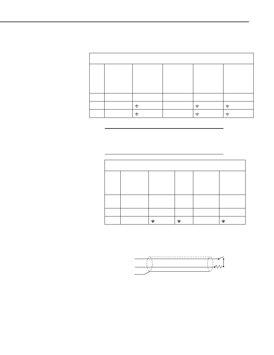
FIGURE 4-1. Rain Gage Schematic
Long cables have appreciable capacitance between the lines. A built up charge
could cause arcing when the switch closes, shortening switch life. A 100 ohm
resistor is connected in series at the switch to prevent arcing by limiting the
current (Figure 4-1). This resistor is installed on all rain gages currently sold
by Campbell Scientific.
9