1 cr800, cr850, cr1000, or cr3000 programming, Cr800, cr850, cr1000, or cr3000 programming, Pass only) – Campbell Scientific CS11-L Current Transformer User Manual
Page 17
CS11-L Current Transformer
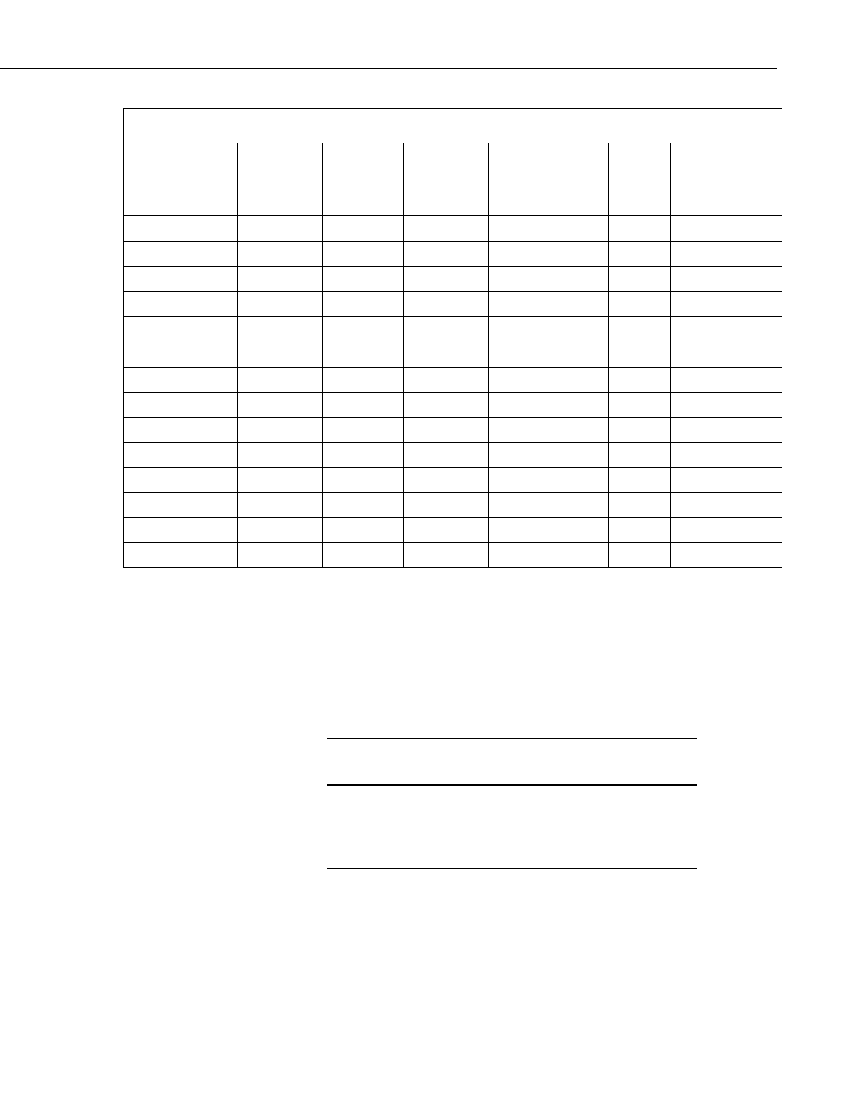
TABLE 6-1. Max Amps on Each of the Range Codes in the Datalogger (one pass only).
Datalogger >>>
Range Codes
(mV)
CR200(X)
Series
CR10X
CR500
CR510
CR1000
CR800
CR850
CR21X CR23X CR3000
Amperage
Resolution
2.5
0.5
0.5
0.000133
5
1
0.000067
7.5
1.5
1.5
0.000400
10
2
0.000133
15
3
0.000200
20
4
0.000134
25
5
5
0.001334
50
10
10
10
0.000666
200
40
40
0.002660
250
50
50
0.013340
500
100
0.006660
1000
200
200
0.013320
2500 125
200
200
0.133400
5000 200
200
200
200
0.066600
6.1 CR800, CR850, CR1000, or CR3000 Programming
With these dataloggers, the best method for monitoring amperage is to make
millivolt burst measurements, and then calculate rms. The millivolt burst
measurements are made by using the VoltSE instruction with multiple reps on
the same channel (for example, negative value for channel number). The
SpaDevSpa instruction calculates rms.
Program must be run in the pipeline mode on CRBasic
dataloggers.
NOTE
It is important to measure complete cycles. If 100 measurements are taken
during a 0.1 second time period, the result will be five complete cycles for a 50
Hz waveform or six complete cycles for a 60 Hz waveform.
Do not average the waveform reading in the data table nor
use the 60 Hz or 50 Hz noise rejection in the measurement
instructions in the program. Doing so would result in an
incorrect zero amperage reading.
CAUTION
11