Campbell Scientific CS10-L and CS15-L Current Transformers User Manual
Page 24
Appendix A. Theory of Operation
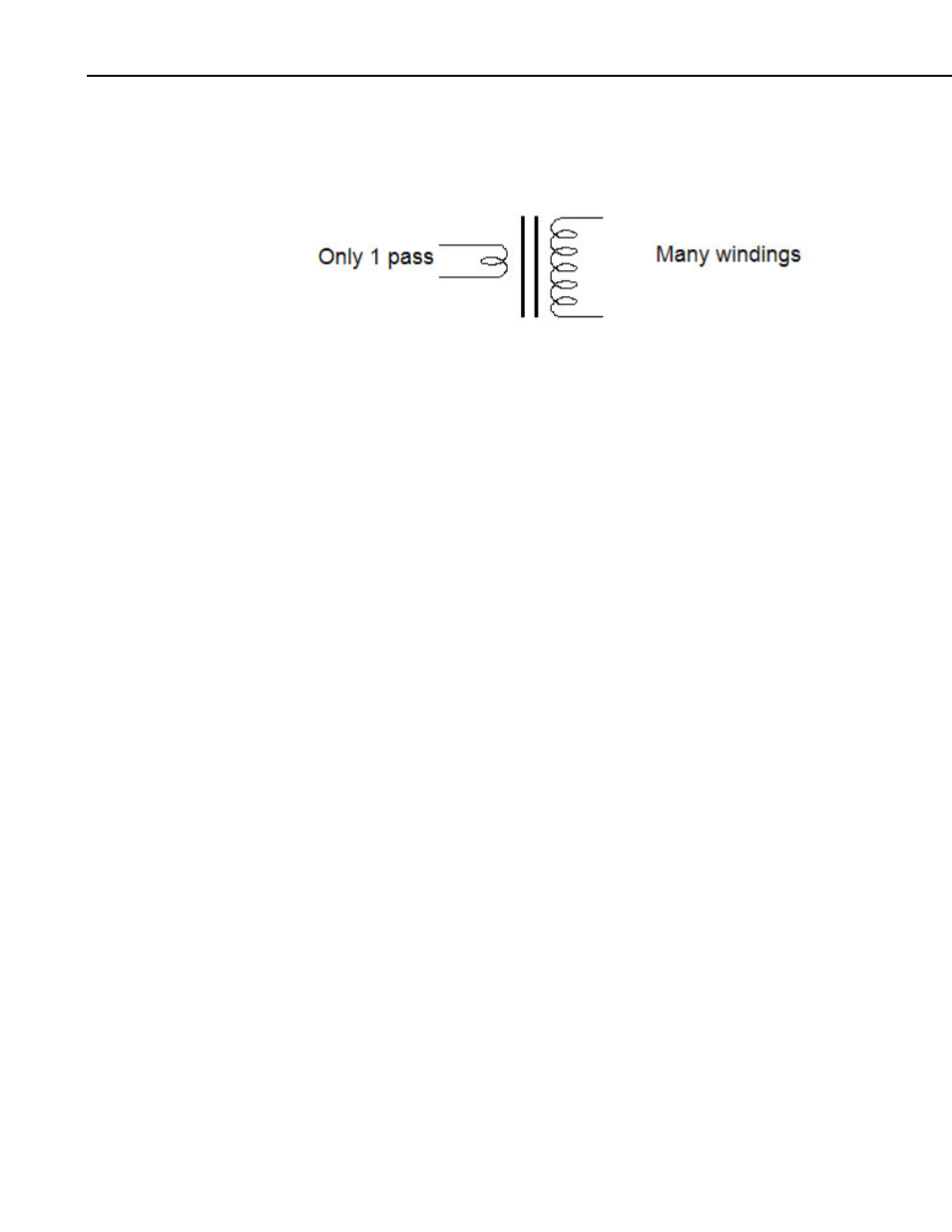
With the current transformer, the primary coils or windings are minimized to
avoid removing power out of the circuit, but still have a signal large enough to
measure (see Figure A-6).
FIGURE A-6. Windings schematic
A tiny bit of the current is transferred to the secondary coil.
We can find the current induced on the secondary windings by solving for i
2
:
i
2
= i
1
* n
1
/n
2
Equation
B
For Example: The CS10 current transducer has an n
2
value of 2000 windings.
If 20 amps pass through the primary winding, the following amperage is
produced on the secondary winding:
i
2
= 20 * (1/2000) = 0.01 amp on secondary winding
A.3 Converting a Milliamp Signal to a Millivolt Signal
After the current is transformed from one level to another level, we need to
convert the amperage signal into a voltage signal so that the datalogger can
measure it.
Use Ohm’s Law (Equation C) to convert amperage to voltage:
E = I * R (E=Volts, I = Amps, R = Ohms)
Equation C
For Example: Using our previous example:
E = 0.01 amps * R
The CS10-L contains a 10-ohm burden (shunt) resistor. Therefore E is:
E = 0.01 amps * 10 ohms = 0.1 volts (or 100 mV)
From these calculations, we can determine if we want slightly better resolution
on the measurement. We can lower the Range Code to 250 mV for some
dataloggers.
A-4