2 datalogger programming, Datalogger programming, 1. 43347-ix – Campbell Scientific 43347 RTD Temperature Probe and 43502 Aspirated Radiation Shield User Manual
Page 20: Temperature probe schematic, 1. datalogger, Connections, Figure 6-1, Table 6-1
43347 RTD Temperature Probe, 43502 and 41003-5 Radiation Shields
When Short Cut software is used to create the datalogger program, wire the
sensor to the channels shown on the wiring diagram created by Short Cut.
Wire Label
Ground
CLEAR
RED
WHITE
GREEN
EARTH GND
+ RTD
+ SENSE
- SENSE
1000 OHM
RTD
43347
Terminals
R
s
Current Excite/+ RTD
Sense Signal
Sense Signal Ref
Current Return/- RTD
BLACK
- RTD
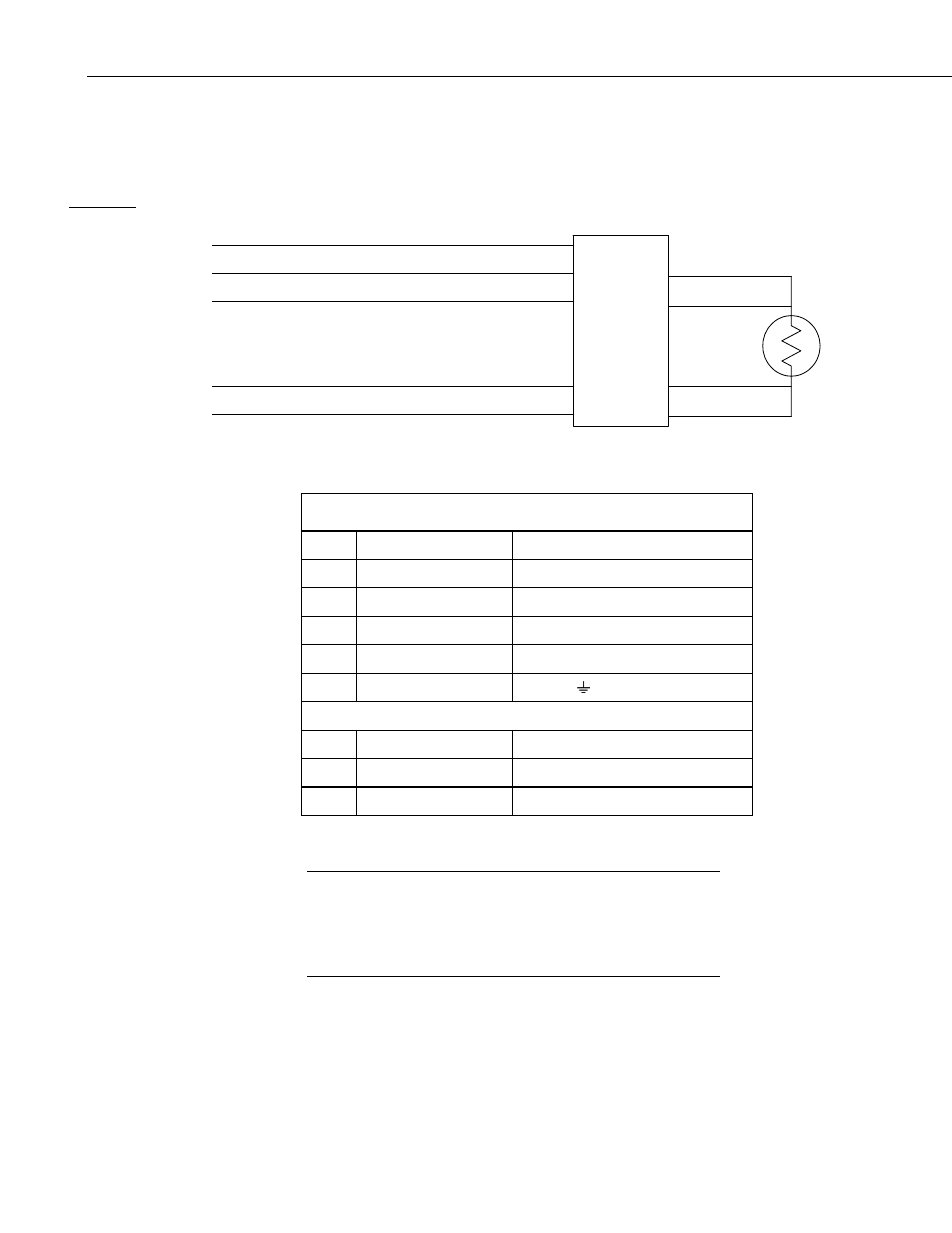
FIGURE 6-1. 43347-IX Temperature Probe schematic
TABLE 6-1. Datalogger Connections
Color Wire Label
CR3000, CR5000
Red
Current Excite/+ RTD Switched Current Excitation
White Sense Signal
Differential (high)
Green Sense Signal Ref
Differential (low)
Black Current Return/- RTD Switched Current Excitation Return
Clear Ground
Ground
( )
43502 Shield
White Tachometer
Red *12V
power
Black *Gound
*wired to the 115 Vac/12 DC transformer supplied with the 43502, or
separate 12 Vdc supply
Occasionally, a customer may need to connect an “IX” version
of the sensor to a datalogger that has voltage excitation only
(e.g., CR10(X), CR800, CR1000). The customer can do this by
using a 4WPB1K terminal input module (refer to the 4WPB1K
manual for more information).
NOTE
6.2 Datalogger Programming
This section is for users who write their own programs. A datalogger program
to measure this sensor can be created using Campbell Scientifics’ Short Cut
Program Builder software. You do not need to read this section to use Short
Cut.
14