Overview – Campbell Scientific 014A Met One Wind Speed Sensor User Manual
Page 15
Met One 014A Wind Speed Sensor
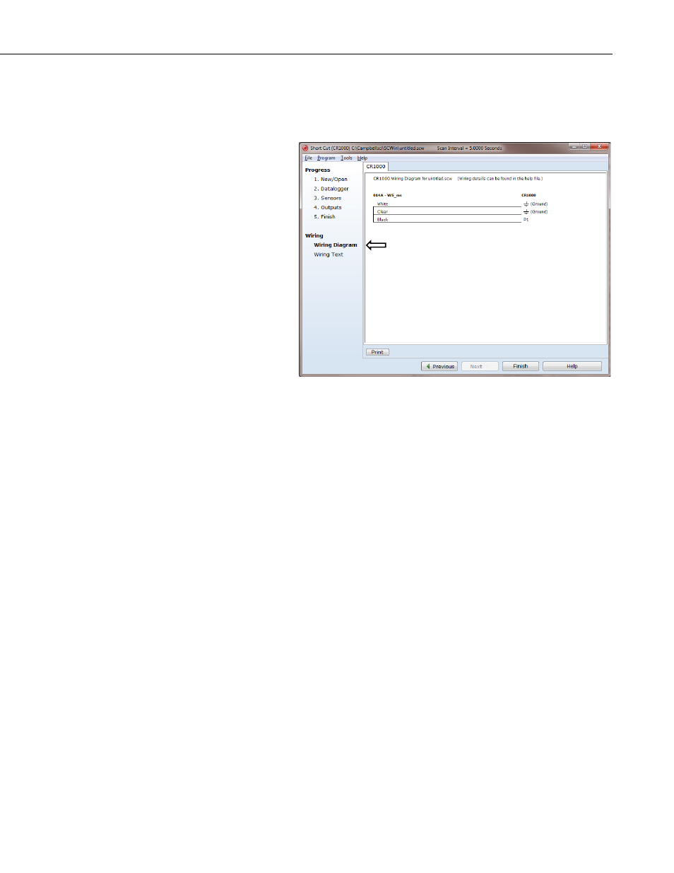
6. After selecting the sensor, click at the left of the screen on
Wiring
Diagram to see how the sensor is to be wired to the datalogger. The
wiring diagram can be printed out now or after more sensors are
added.
7. Select any other sensors you have, then finish the remaining Short Cut
steps to complete the program. The remaining steps are outlined in
Short Cut Help, which is accessed by clicking on
Help | Contents |
Programming Steps.
8. If LoggerNet, PC400, RTDAQ, or PC200W is running on your PC,
and the PC to datalogger connection is active, you can click
Finish in
Short Cut and you will be prompted to send the program just created
to the datalogger.
9. If the sensor is connected to the datalogger, as shown in the wiring
diagram in step 6, check the output of the sensor in the datalogger
support software data display to make sure it is making reasonable
measurements.
5. Overview
The 014A is constructed of corrosion-resistant, stainless-steel and anodized
aluminum. Its three-cup anemometer assembly contains a sealed magnetic reed
switch. Rotation of the cup wheel produces a pulse that is directly proportional
to wind speed.
The accompanying Met One manual contains additional information on
operating principals, installation, and maintenance.
The –L portion of the model number indicates that the 014A has a user-
specified cable length. TABLE 5-1 gives the recommended lead length for
mounting the sensor at the top of the tripod/tower with a CM202 crossarm.
7