2 calibration and orientation, Calibration and orientation, 2. parameters – Campbell Scientific 024A-L Met One Wind Direction Sensor User Manual
Page 16: Wind direction
024A Met-One Wind Direction Sensor
codes, and delays for CSI dataloggers are listed in TABLE 7-2. The process
for determining the correct multiplier is provided in Section 7.4.2, Calibration
and Orientation.
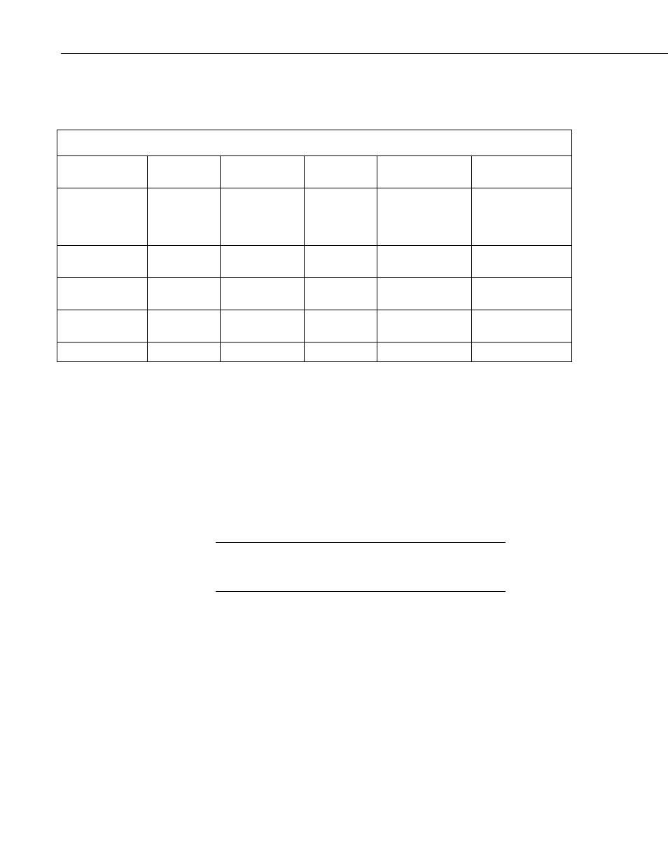
TABLE 7-2. Parameters for Wind Direction
CR200(X)
CR10(X),
CR510
CR7, 21X,
CR23X
CR800, CR850,
CR1000
CR5000,
CR3000
Measurement
Range
2500 mV
250 mV, fast
500 mV, fast
2500 mV,
250 microsecond
integration,
reverse excitation
5000 mV,
250 microsecond
integration, reverse
excitation
Excitation
Voltage
2500 mV
500 mV
1000 mV
2500 mV
5000 mV
Delay or Settling
Time
2 ms
2 ms
2 ms
2 ms
2 ms
Multiplier See
Section
See Section
7.4.2
See Section
7.4.2
See Section 7.4.2
Offset 0 0 0 0
0
7.4.2 Calibration and Orientation
Conversion of the voltage output into wind direction is done by entering the
proper multiplier. The proper multiplier is calculated by dividing 360 by the
full scale input voltage (i.e., 360/FSIV). The full scale input voltage (FSIV) is
the maximum voltage output from the wind vane. This is found by creating a
datalogger program with a multiplier of 1, the default excitation, and a fast
scan interval. With a multiplier of 1, the value stored in the variable or input
location is simply the voltage output. Slowly turn the wind vane; the shoulder
screw must first be removed. The maximum value observed is the full scale
input voltage (FSIV).
If the reading is -99999, exceeds 500 on the 21X or CR7, or
exceeds 250 on the CR10, then reduce the millivolts of excitation
by 5 mV.
NOTE
Multiplier 360/FSIV*
Offset 0.0
*FSIV = Full scale input voltage
Enter the calculated multiplier in the program.
Orientation of the 024A Wind Direction Sensor should be complete if the 024A
counter weight was aligned due south.
10