3 wiring, 4 programming, 1 datalogger instruction – Campbell Scientific 024A-L Met One Wind Direction Sensor User Manual
Page 15: Wiring, Programming, Datalogger instruction, 3. schematic of 024a wind direction sensor, 1. connections to campbell scientific dataloggers
024A Met-One Wind Direction Sensor
7.3 Wiring
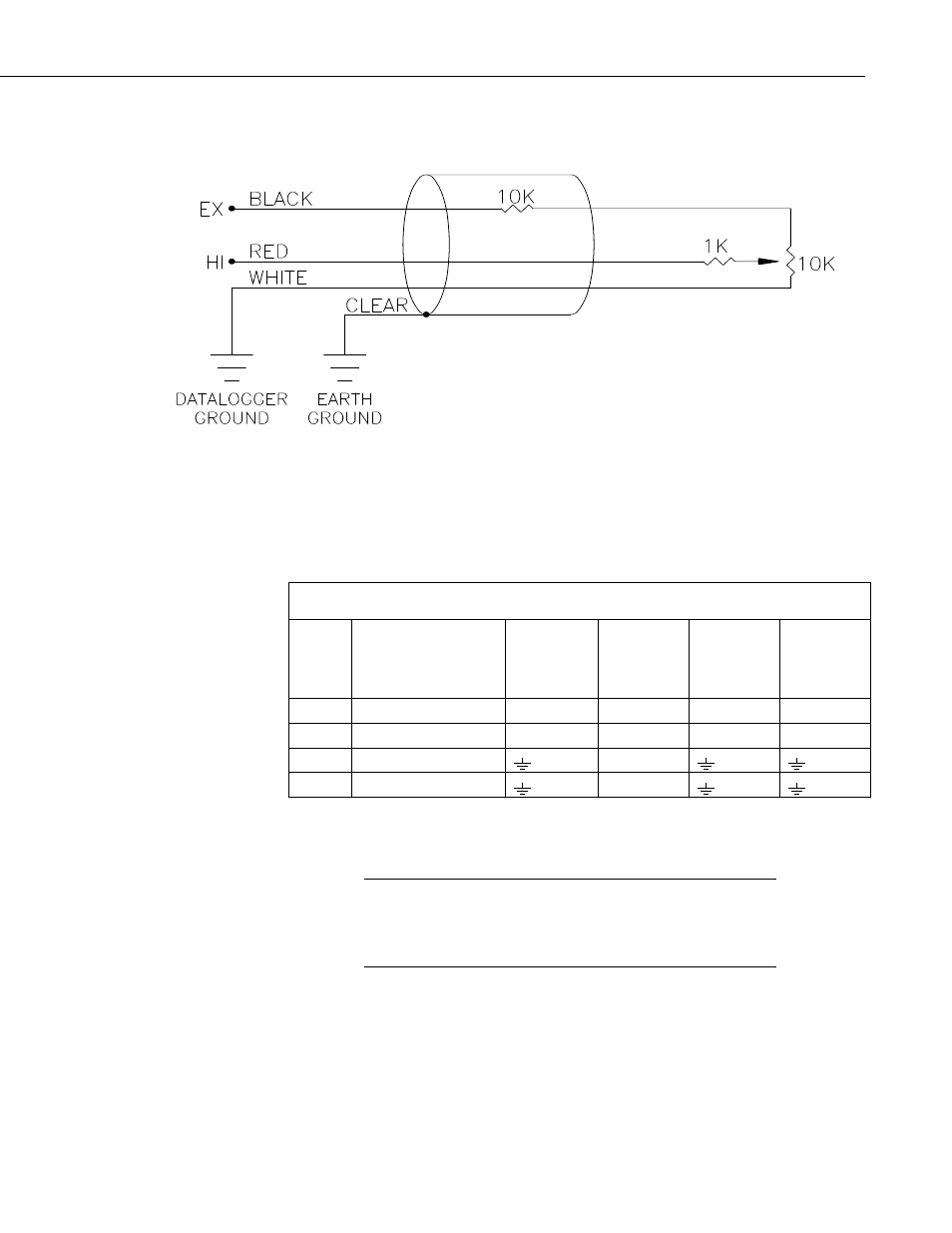
FIGURE 7-3. Schematic of 024A Wind Direction Sensor
FIGURE 7-3 and TABLE 7-1 shows wiring; a detailed cable diagram is
provided in Section 8, Maintenance (FIGURE 8-1). When Short Cut is used to
create the datalogger program, the sensor should be wired to the channels
shown on the wiring diagram created by Short Cut.
TABLE 7-1. Connections to Campbell Scientific Dataloggers
Color
Description
CR800
CR5000
CR3000
CR1000
CR510
CR500
CR10(X)
21X
CR7
CR23X
CR200(X)
Red
Wind Dir. Signal
SE Analog
SE Analog
SE Analog
SE Analog
Black Wind
Dir.
Excitation Excitation Excitation Excitation Excitation
White Wind
Dir.
Reference
AG
Clear Wind
Dir.
Shield
G
7.4 Programming
This section is for users who write their own programs. A
datalogger program to measure this sensor can be created using
Campbell Scientifics’ Short Cut Program Builder software. You
do not need to read this section to use Short Cut.
NOTE
7.4.1 Datalogger Instruction
The datalogger instruction that measures the 024A is datalogger dependent.
The BRHalf() measurement instruction is used for our CR800, CR850,
CR1000, CR3000, and CR5000 dataloggers. Our CR200(X)-series dataloggers
use the EX-DEL_SE(). Our Edlog dataloggers (e.g., CR510, CR10(X),
CR23X) use Instruction 4 – Excite, Delay, Measure. Excitation voltages, range
9