10 | samlex america inc. samlex america inc. | 11 – Samlex America MSK-135 User Manual
Page 11
10 | SAMLEX AMERICA INC.
SAMLEX AMERICA INC. | 11
SectIOn 3 |
Installation & Operation
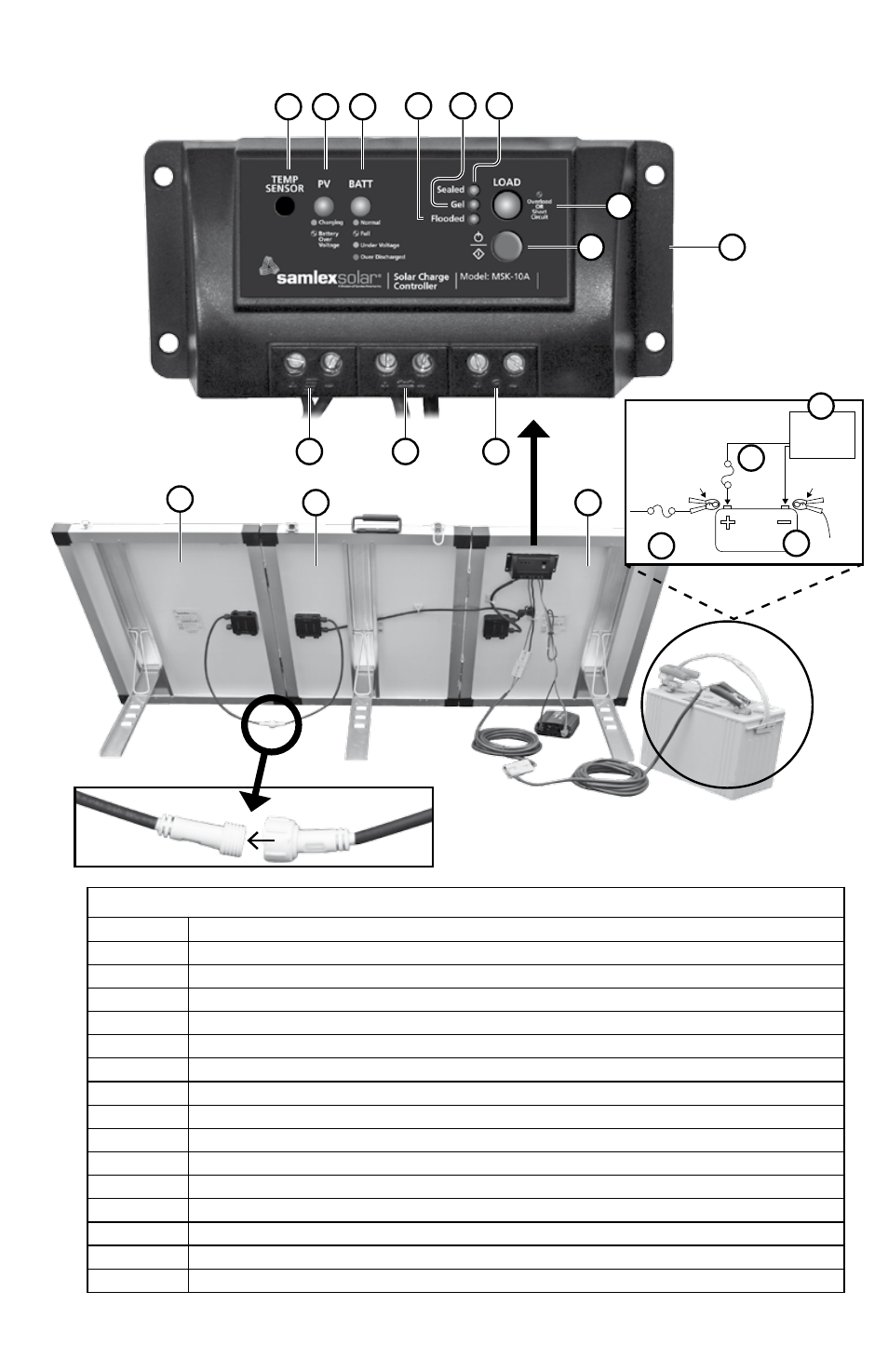
Fig 3.2 MSK-135 LAYoUt
1, 2, 3
3 x 45W Solar Modules connected in parallel (MSK-90 has 2 x 45W Solar Modules 1 & 2)
1A, 2A, 3A
45W Module Junction box
4, 4A, 4b
2-Pole Mating Connector (for MSK-135) for connecting third Module 3 in parallel with Modules 1 & 2
5 / 5I
Charge Controller MSK-10A (5) / Charge Controller Terminals for Solar Array (5i)
5J / 5K
CHArGe CoNTroLLer TerMINALS: for battery (5J) / for DC Load up to 10A (5K)
5G
Status LeD "Load"
5H
Setting button
6
10A fuse with fuse Holder
7,8A,8b,9A
50A Anderson Type Sb50 Compatible Mating Connectors
8
16 ft extension Cable for battery Connections
9
16 ft Cable for battery Connection
9b, 9C
Alligator Clips for battery Connection: 9b - Positive; 9C - Negative
10
10A fuse inserted within 3" from Positive battery Alligator Clip 9b (fuse not supplied)
11
12V battery
12
fuse for DC load(s) within 7" of battery and Terminal (not supplied)
13
DC load(s) drawing > 10A
5A
5b
5C
5D
5e
5f
5G
5H
5I
5J
5K
3
2
1
3A
2A
4
6
4A
4b
1A
5
8
8A
8b
9A
9
7
9C
5
11
DC Load
> 10A
Fuse
Battery
+ Battery
Clamp 9B
Fuse
- Battery
Clamp 9C
12
11
10
13