4. configuration in usb mode, 5. panel id setting (usb mode) – DMC TSC-30/IC User Manual
Page 9
Document No. DER-S0098A
8
Version 1.3 ©2012 DMC Co., Ltd.
TSC-30/IC Product Specification
JP4
V
CC
(TSC-30/IC)
V
CC
JP5
H
L
H
L
4-4. Configuration in USB mode
§ Basic configuration
Item
Specification
USB standard
Specification Rev2.0 Full Speed
Power supply
Bus power supply / Self-Power
Device class
Vendor definition
Interrupt (coordinate)
transfer interval
1ms
End point buffer size
EP0: 8byte EP1: 5byte (EP0: control transfer, EP1: interrupt transfer)
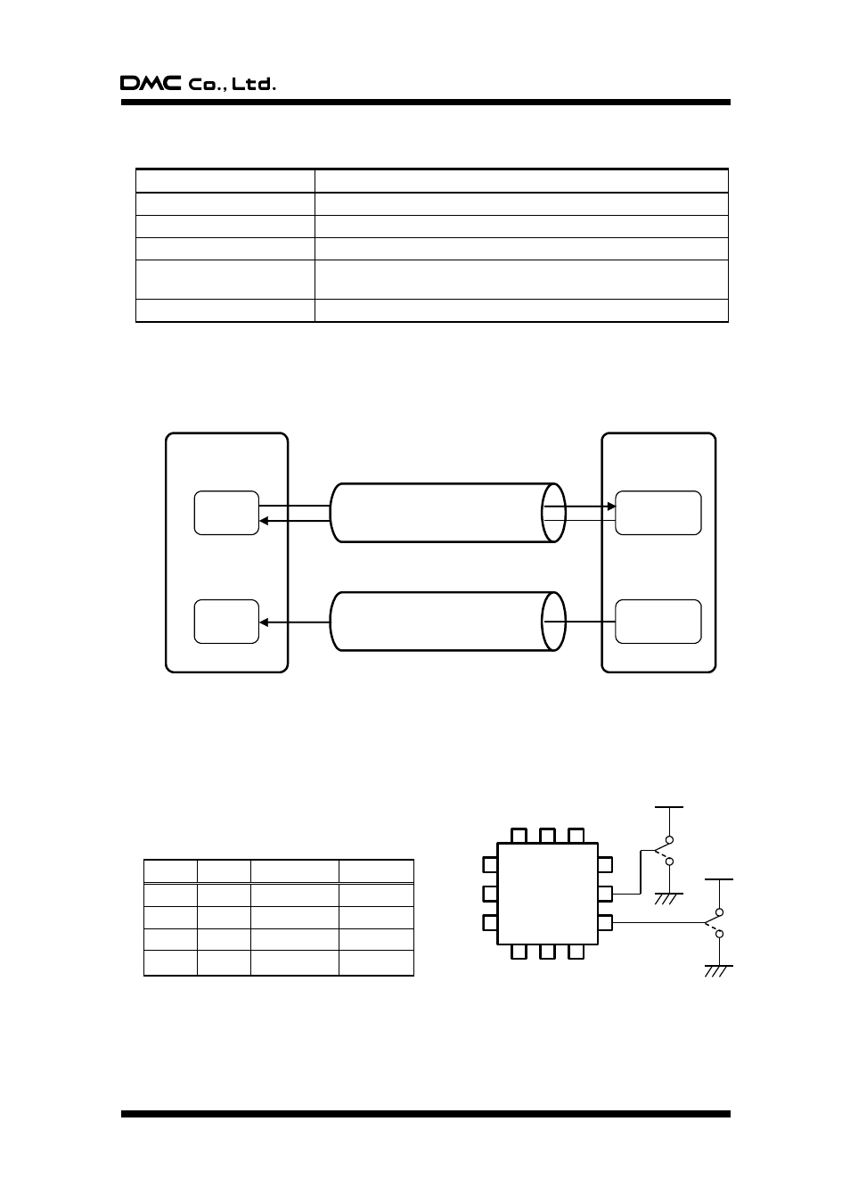
§ Connection with Host
Coordinate data, correction value or other various output data are all output to the host as a response
to IN token. Output coordinate in coordinate data mode and correction data mode is output in the
interrupt transfer, while other data is output to the host with control transfer.
4-5. Panel ID setting (USB mode)
If two (three or four) touch screens to the same host are connected simultaneously, each TSC-30/IC to the
host needs panel ID setting. This function is enabled in the USB mode, by setting pin number 58 (JP4) and
pin number 59 (JP5) to “ H” or “ L” . Setting is enabled when hardware is reset, where Device
Descriptor’ s iProduct is set to “ 0” or “ 1” and this value
is identified by the host as panel ID.
JP4
JP5
iProduct
Panel ID
L
L
00h
0
H
L
01h
1
L
H
02h
2
H
H
03h
3
Host
TSC-30/IC
End Point 0
IN/OUT
Control transfer
(Descriptor, Device Request (command))
Interrupt transfer
(Coordinate data)
End Point 1
IN
Buffer
Buffer