Part 2 service – Midco G69B User Manual
Page 9
AIR
ONLY
1.00
0.87
0.70
0.55
0.42
0.31
0.22
0.08
1.90
1.43
1.22
0.84
0.68
0.41
0.30
0.08
2.65
2.24
1.98
1.74
1.11
0.77
0.50
0.19
2.25
1.74
1.44
1.17
0.81
0.52
0.36
0.23
-9-
PART 2
SERVICE
CAUTION: BE SURE THAT THE MAIN MANUAL
SHUT-OFF, MANUAL PILOT VALVE, AND POWER
DISCONNECT BURNER SWITCH ARE TURNED OFF
BEFORE REMOVING ANY PARTS FOR SERVICE.
CAUTION: COVER PLATES, GUARDS, AND
ENCLOSURES MUST BE IN PLACE AT ALL TIMES
EXCEPT DURING MAINTENANCE AND SERVICE.
VIII
BURNER BOX AND FIRING HEAD
The UNIPOWER burner head is of the nozzle mixing
(non-premix), flame retention type. This design
accommodates a high capacity without flame lift off and a
low capacity without flash back.
The burner box serves as an air plenum chamber and a
frame to which all other parts are assembled. Blower air
enters the box and passes around the outside of the gas
manifold and through the retention plate. Gas passes
through ports in the manifold, then through the retention
plate where it is mixed with the blower air by turbulence
caused by the retention plate, and into the combustion
chamber for burning. The gas ports are not adjustable.
Variation in capacity is accomplished by a variation in gas
pressure.
Maintenance of the burner box and firing head is minimal,
due to the simplicity of the parts and absence of small air
or gas passages. An occasional inspection of the parts in
contact with the flame will suffice. The flame retention
plate must show no loss of metal or severe warping. If the
heads of the retention plate mounting screws show loss of
metal they must be replaced. Use only stainless steel
screws.
Stainless nozzle sleeve must extend at least 1/2"
beyond flame retention plate.
If the burner mounting flange or adjacent furnace wall
show signs of overheating, check the tightness of the
burner mounting. The burner is intended to be sealed into
the boiler opening both at the face and at the mounting
flange as shown in Figure 4, to prevent blow-back of hot
flue products around the nozzle and flange.
IX
PILOT AND FLAME SENSOR
The pilot is of the premix, blast type. Blower air is diverted
from the blower housing through an air orifice into the pilot
mixing tee mounted on the burner back plate, where the
proper amount of gas is added through the pilot orifice.
Both orifices are located at the end of their own respective
tubes in brass fittings leading into the mixing tee. The
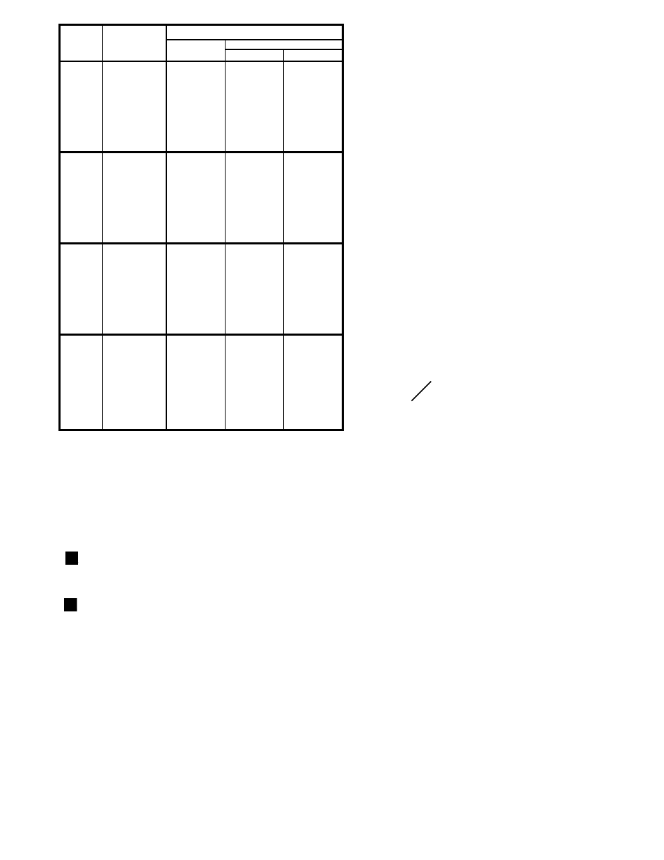
MODEL
G56B
G57B
G58B
G69B
CAPACITY
MBH*
1075
1000
900
800
700
600
500
300
1500
1300
1200
1000
900
700
600
300
1850
1700
1600
1500
1200
1000
800
500
2500
2200
2000
1800
1500
1200
1000
800
NATURAL
2.10
1.82
1.47
1.16
0.89
0.65
0.45
0.16
4.10
3.08
2.62
1.82
1.48
0.89
0.66
0.16
4.60
3.88
3.44
3.02
1.94
1.34
0.86
0.34
4.15
3.21
2.66
2.15
1.49
0.96
0.66
0.42
PROPANE
1.45
1.25
1.01
0.80
0.61
0.45
0.31
0.11
2.79
2.10
1.79
1.24
1.01
0.61
0.45
0.11
3.75
3.17
2.80
2.47
1.58
1.10
0.70
0.27
3.65
2.83
2.34
1.89
1.31
0.84
0.58
0.37
MANIFOLD PRESSURES ("W.C.)
GAS ON
This table is provided as a guide to use the INPUT
ADJUSTING METHOD to approximate final settings.
The valve train MUST be tested for tightness and the pilot
adjusted for proper operation before proceeding. Refer to
Section VIII of the Installation and Service Instructions
.
1.
Install a Manometer (not a pressure gauge) in the
manifold pressure tap.
2.
Close the Main Manual Gas Valve.
3.
Close the Input Adjuster (butterfly valve).
4.
Turn the burner on.
5.
Adjust the air shutter to the ÒAir OnlyÓ pressure shown
for the desired MBH.
6.
Open the Main Manual Gas Valve.
7.
Slowly open the Input Adjuster until the observed
manifold pressure equals the Gas On pressure for the
desired MBH.
8.
Take combustion readings and confirm the input rate by
clocking the gas meter.
9.
Adjust the air shutter and/or the Input Adjuster as
needed.
10. Repeat steps 8 and 9 until you have the desired input
rate with clean combustion**.
11.
Refer to section VIII of the Installation and Service
instructions for final Main Gas Regulator adjustment
procedures.
For capacities not shown:
P
2
= P
1
x
(
MBH
2
MBH
1
*1 MBH=1000 BTU/Hr
**Approximately 25% excess air (4.5% O
2
)
)
2
ALL FIGURES ARE APPROXIMATE. Actual figures will vary depending upon application and ambient conditions.
Based on 0 pressure over the fire at Standard Air and Specific Gravities of .64 for NATURAL GAS, and 1.52 for
PROPANE GAS. It is the responsibility of the installer to make final adjustments to insure proper and safe operating
conditions, and to comply with all codes and guidelines that may apply at the installation site. Contact the local Utility for
any requirements and recommendations they may have. In the absence of any local codes, guidelines or requirements,
refer to the latest edition of the National Fuel Gas Code, ANSI Z223.1-1992.
TABLE 4: Approximate ÒGÓ Series Capacities At Specified Manifold Pressures.