Part 1 installation, Specifications, I ventilation – Midco G69B User Manual
Page 2
NATURAL
5.0" W.C.
7.0" W.C.
6.7" W.C.
7.5" W.C.
INLET GAS PRESSURE
REQUIRED2
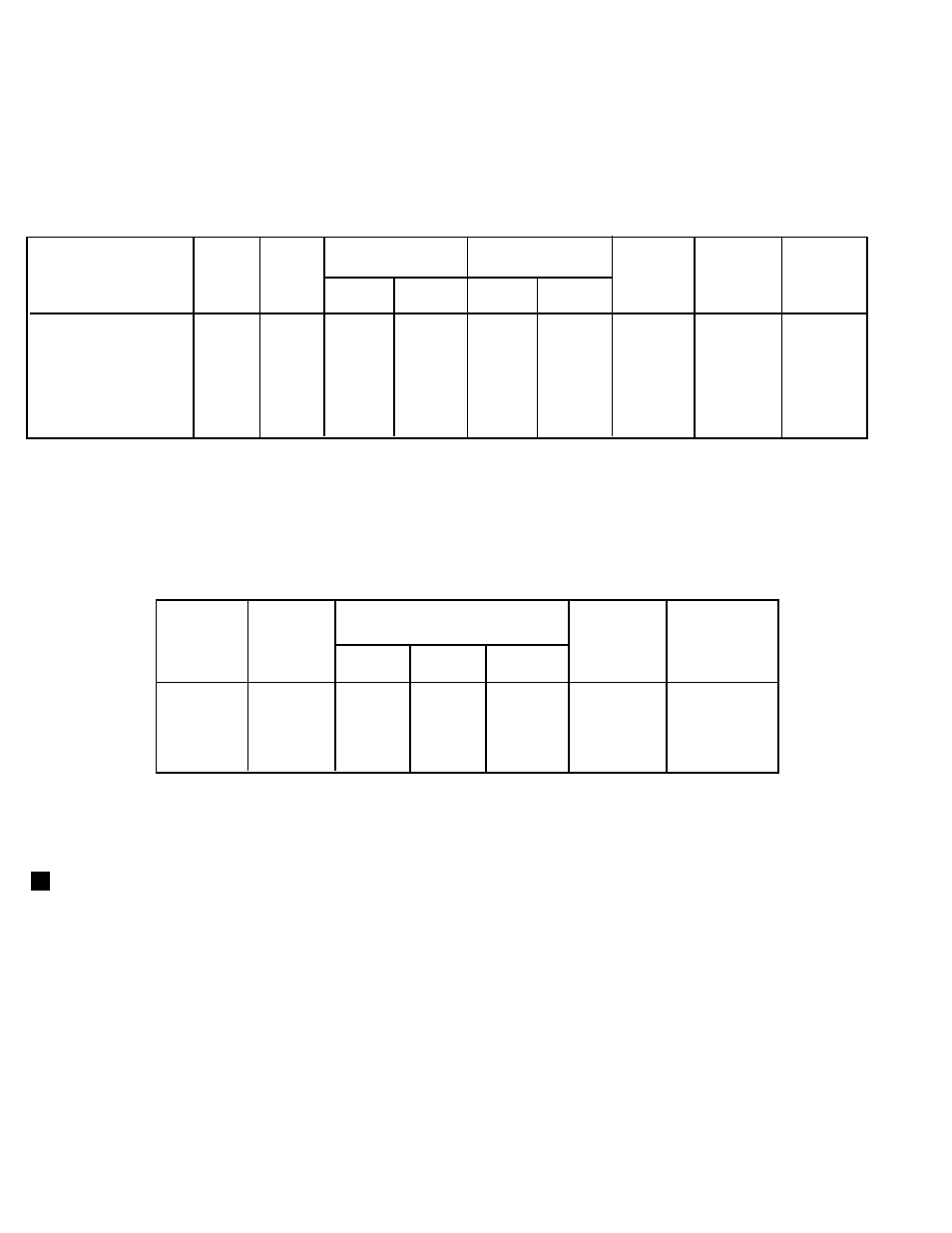
TABLE 2
Maximum Capacity at Specified Back Pressures
PART 1
INSTALLATION
CAUTION: Unipower GB -Series are not intended
for outdoor installation and must be protected from
excessive moisture. Provide adequate clearance for
service and proper operation.
I VENTILATION
Open basements will generally allow sufficient air
infiltration, so special provisions will seldom be required. If
the heating plant is located in a separate furnace room or
in an unusually tight basement, permanent means must be
provided to supply an ample volume of fresh air for
combustion and boiler room ventilation. A direct opening
to the outside air should be provided sized on the basis of
1/2 square foot of free opening for each 1,000,000 BTU of
burner rating when the vent connector is equipped with a
barometric draft control, 1 1/2 square feet when equipped
with a draft hood. If the ventilation opening is screened, it
should be of 1-1/4" mesh. The opening should be located
at least six feet over ground level to prevent accidental
obstruction. If a direct opening to the outside air is not
available, an ample sized air duct can be run to the
nearest outside air source; or, if practical, open stairwells
or building corridors connecting to an outside wall having a
ventilating opening can be used for this purpose, provided
that no possibility of accidental closure exists.
While the spark ignition pilot system performs successfully
under moderate or momentary back draft conditions, it is
not intended for operation under sustained reverse draft,
for example in a building with large ventilating fans but with
insufficient make-up air. Even if burner operation is
successful this condition must be corrected to prevent the
hazard of drawing flue gases into the building.
Consult your local gas company when doubt exists
concerning boiler room ventilation.
SPECIFICATIONS
BURNER STYLE...................................................................... Power Type
PILOT TYPE............................................................................. Intermittent, Spark Ignition
PILOT SAFETY........................................................................ Instantaneous Electronic Flame Safeguard
STANDARD VOLTAGE
CONTROLS (FIELD WIRING)...............................................120/1/60
MOTOR................................................................................. 115/1/60 (except G69B-115/230/1/60)
U.L. LISTED
NATURAL Gas
(1,000
BTU/cu. ft.)
G56B
G57B
G58B
G69B
PROPANE Gas
(2,500
BTU/cu. ft.)
G56BP
G57BP
G58BP
G69BP
Maximum
Input
1
MBTU/Hr.*
1000
1450
1800
2500
PROPANE
5.0" W.C.
5.0" W.C.
6.0" W.C.
8.0" W.C.
NATURAL
2.2" W.C.
4.1" W.C.
4.6" W.C.
4.2" W.C.
PROPANE
1.2" W.C.
2.6" W.C.
3.8" W.C.
3.3" W.C.
Minimum Input
3
MBTU/Hr.*
300
300
500
800
Motor HP
(3450 RPM)
1/6
1/3
1/2
3/4
Recom-
mended
Combustion
Chamber Size
42" x 18
"
48" x 21"
50" x 24"
60" x 27"
TABLE 1
Burner Specifications
1.
Values given based on +0.000" W.C. firebox pressure, altitudes to 2000 feet. Derate burner for altitudes over 2000
feet by 4% for each 1000 feet over sea level.
2.
Maximum inlet pressure both gases: 14" W.C. Refer to Section VI Piping for high pressure.
3.
Modulating and two-step burners are limited to a 3 to 1 turndown ratio.
4.
Manifold pressures are approximate and will vary slightly according to job condition. See Section VII para. 11.
5.
Pressures are based on 25% excess combustion air.
6.
SCFM = Standard Cubic Feet/Minute.
MODEL
G56B
G57B
G58B
G69B
MINIMUM
FIRING RATE
MBH*
300
300
500
800
0" W.C.
1075
1500
1850
2500
.25" W.C
.
950
1400
1750
2375
.5" W.C.
875
1325
1650
2275
MAXIMUM BACK
PRESSURE
IN " W.C.
0.7
0.8
1.0
1.0
MAXIMUM MBH* @
MAX. B.P.
700
1325
1400
2100
MAXIMUM CAPACITY IN MBH AT
COMB. CH. - BACK PRESSURE
* 1 MBH = 1,000 BTU/Hr.
MODEL
BURNER MANIFOLD
PRESSURE
1, 4, 5
-2-
Maximum
Air
SCFM
6
224
313
385
521