Cables, Figure 2-3. flex cable pin 1 location, Figure 2-4. flex cable pin list – MagTek SWIPE & PARK User Manual
Page 15: Figure 2-5. pitch and mating connector, Switch
Section 2. Installation
7
CABLES
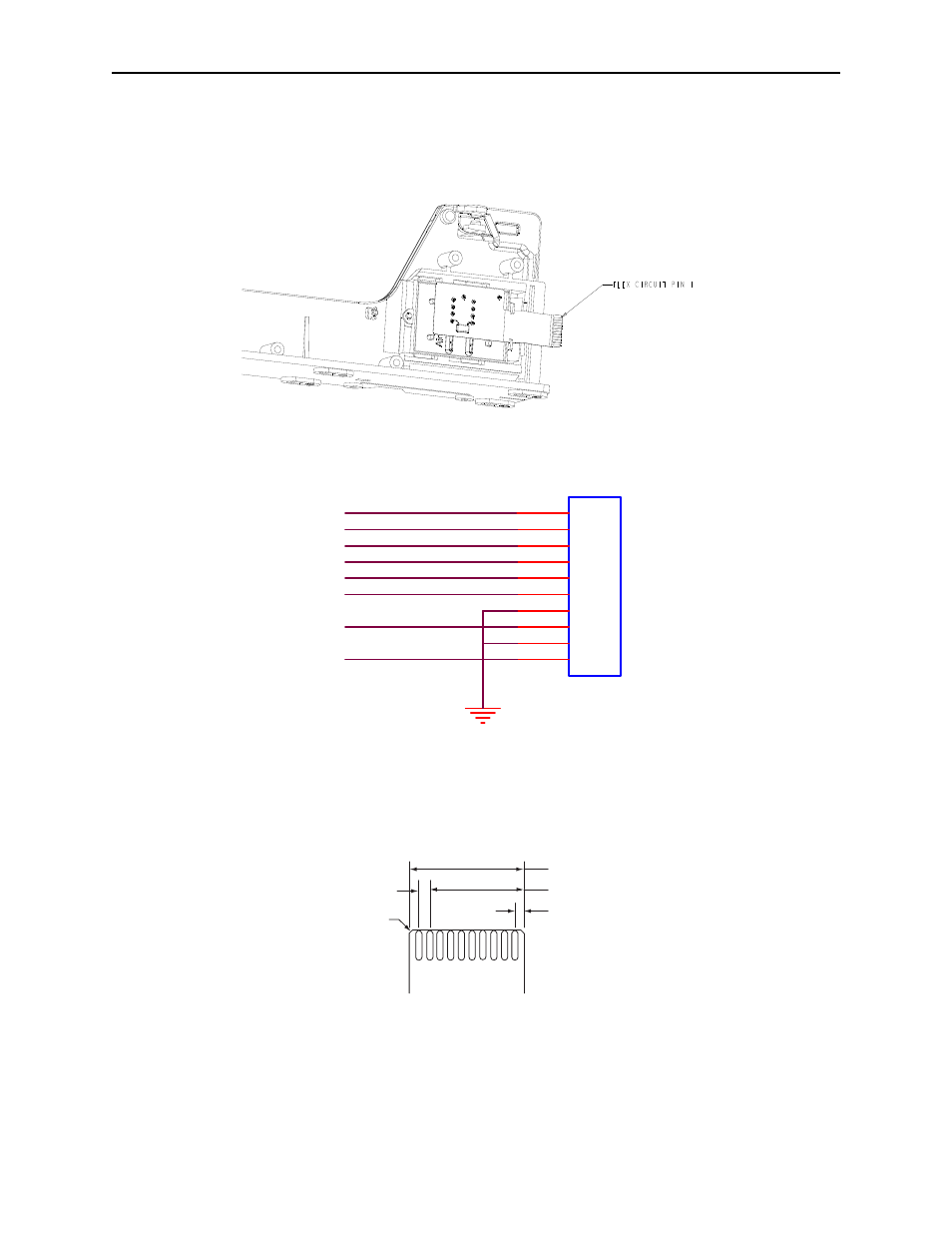
Figure 2-3 shows the location of Pin 1 on the flex cable with respect to the Reader. The pin list
for the flex cable in shown in Figure 2-4. Wiring for the head is shown in Appendix A.
Figure 2-3. Flex Cable Pin 1 Location
nCARDSEATED
SWITCH
J2
1
10PIN
3
2
4
5
6
7
8
9
SC_C2
SC_C1
SC_C6
SC_C8
SC_C4
SC_C3
SC_C7
10
Note:
The Host Interface must provide pull-up for card-seated switch.
Figure 2-4. Flex Cable Pin List
Figure 2-5 shows the pitch and mating connector of the flex cable:
.433" + .004" -.002"
.039" +/- .006"
Termination Detail.
Foil Side Shown.
Mates with Molex
71220 (or equivalent)
Scale: None
.039" (1.0 mm pitch)
.012" x .012"
Chamfer or Radius
2 Places
1
10
Figure 2-5. Pitch and Mating Connector
See also other documents in the category MagTek Equipment:
- USB MagnePrint Swipe Reader with Encryption (72 pages)
- USB HID Swipe Reader (25 pages)
- USB MagneSafe Swipe and Insert Reader V5 (28 pages)
- Bluetooth MagneSafe V5 Swipe Reader (88 pages)
- MagneSafe V5 (138 pages)
- DynaPro99875265 (2 pages)
- IPAD99875382 (26 pages)
- IPAD99875395 (2 pages)
- DynaPro Mini Programmer's99875629 (114 pages)
- Excella, MICR Check Reader99875310 (49 pages)
- Excella Windows API99875313 (104 pages)
- IMAGESAFE WINDOWS API99875500 (109 pages)
- Excella API OCX99875557 (22 pages)
- Excella USB RNDIS99875491 (16 pages)
- Excella99800048 (2 pages)
- MICRSafe99875466 (79 pages)
- Excella STX99875340 (137 pages)
- Excella STX99875342 (47 pages)
- Excella STX99875344 (2 pages)
- MICRSafe99875516 (2 pages)
- EC500 99875172 (49 pages)
- EC500 99875171 (1 page)
- EC2000 99875646 (2 pages)
- EC2000 99875600 (83 pages)
- EC2000 99875607 (180 pages)
- EC2000 99875651 (18 pages)
- EC2000 99875692 (12 pages)
- EC2000 99875713 (21 pages)
- EC2000 99875631 (5 pages)
- EC500 99875170 (2 pages)
- EC1000 99875417 (2 pages)
- MODEL MT-85 (22 pages)
- InSpec 9000 (90 pages)
- InSpec 9000-2005 (86 pages)
- INTELLISTRIPE 380 USB/RS-232 (31 pages)
- MCP (48 pages)
- MAGTEK (80 pages)
- IntelliCAT99875658 (14 pages)
- IntelliCAT99875659 (5 pages)
- IntelliCAT99875662 (7 pages)
- IntelliCAT99875663 (6 pages)
- IntelliCAT99875664 (8 pages)
- IntelliCAT99875667 (6 pages)
- IntelliCAT99875669 (5 pages)
- 99875125 (128 pages)