MagTek IntelliStripe 60 99875135 User Manual
Page 17
Section 2. Installation
9
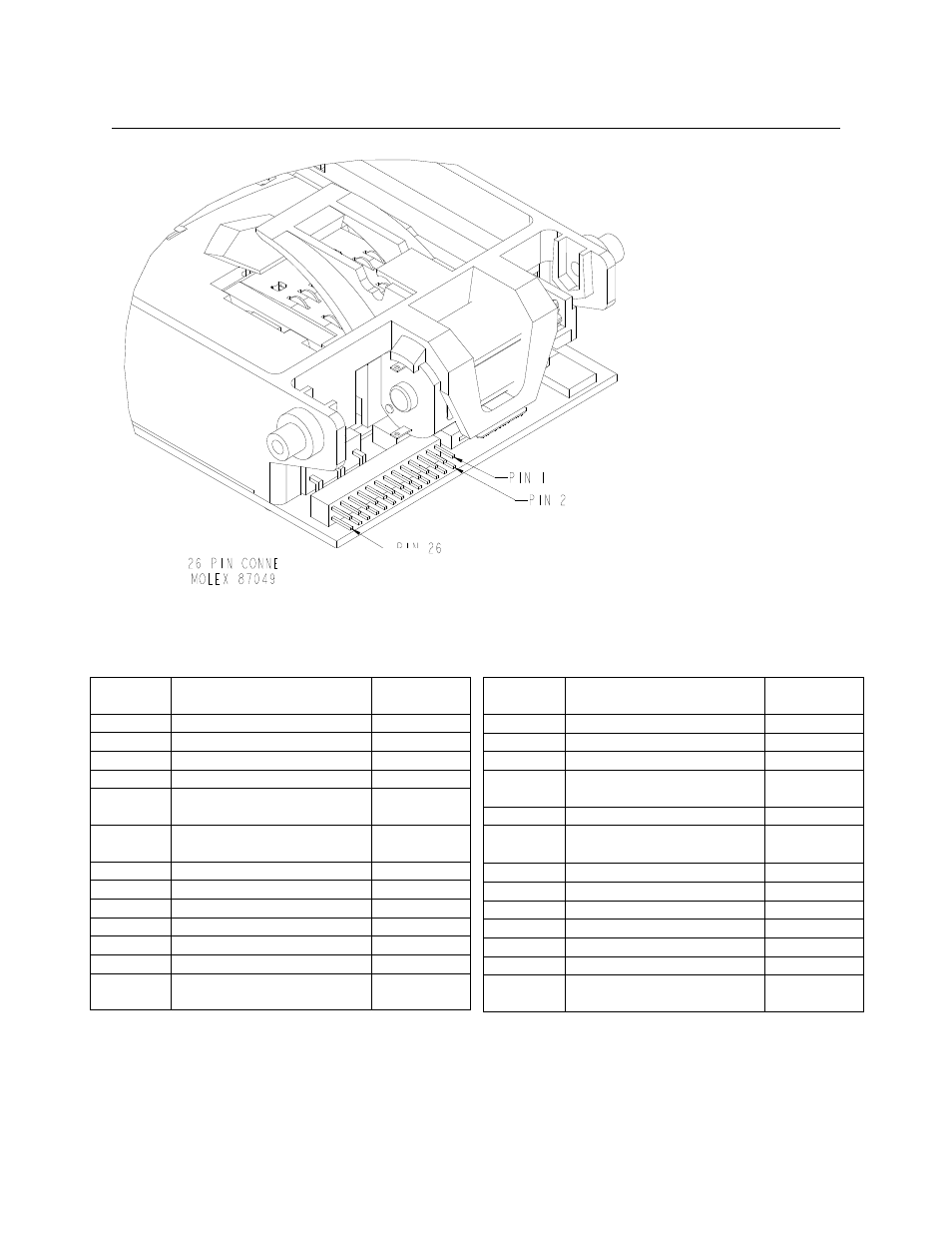
Figure 2-4. Fixed I/O connector Location and Pin Numbers
Table 2-1. Pin List for 26-pin I/O Connector (J12)
Pin
Number
Signal Name
I/O
Direction
1
ICC-C1 Power
IN
2
ICC-C2 Reset
IN
3
ICC-C3 Clock
IN
4
ICC-C4 RFU
-
5
ICC-C5 Ground
(Common to Pins 13, 17)
IN
6
ICC-C6 Programmable
Power
IN
7
ICC-C7 Data
IN/OUT
8
ICC-C8 RFU
-
9
1, 3
Card Present Switch
OUT
10
1, 3
Card Seated Switch
OUT
11
+VCC
IN
12
Latch Control
IN
13
Circuit Ground (Common
to Pins 5, 17)
IN
Notes:
1
= Active Low
2
= Mag Data outputs on pins 15, 23, 25 are normally referenced as: Low = "1" bit, High = "0" bit.
3
=
10K pull-up resistors required on pins 9, 10, 18
Pin
Number
Signal Name
I/O
Direction
14
NC, Reserved
15
2
Mag Data, Track 2
OUT
16
1
Mag Strobe, Track 2
OUT
17
Latch Motor Gnd
(Common to Pin 5, 13)
IN
18
1, 3
Card Latched Switch
OUT
19
Latch Motor
−
Motor Voltage
IN
20
1
Mag Read Enable
IN
21
NC, Reserved
22
1
Mag Media Detect
OUT
23
2
Mag Data Track 1
OUT
24
1
Mag Strobe Track 1
OUT
25
2
Mag Data Track 3
OUT
26
1
Mag Strobe Track 3
OUT
Note
26-pin Header, Molex 87049-2616
mates with Molex 87568-2661, flat
cable 3625/26 mfg by 3M; or mates
with Molex 51110-2650, terminal
50394-8051 (wires).