3 board description, 4 connection of the power supply line, 1 type of cable – Videotec HOV User Manual
Page 9
Instruc
tions manual - English - EN
7
MNVCHOV32_1351_EN
6.1.3 Board description
Connect the safety earth to the relative
terminal of the J1 connector.
The board may appear different to that
illustrated.
Depending on the product version, the
board may not be equipped with all
functions.
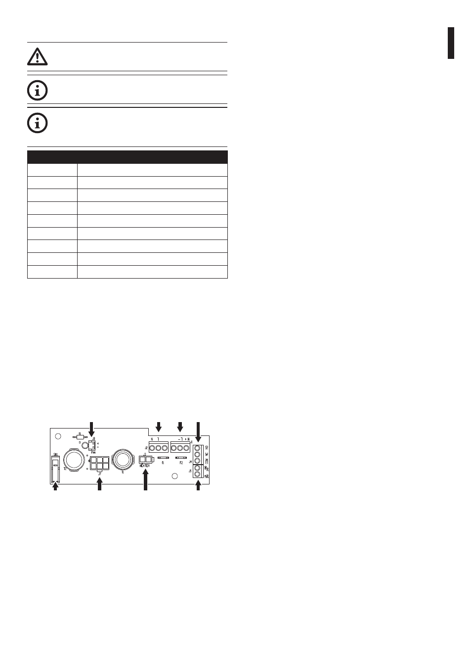
BOARD DESCRIPTION
Connector
Function
J1
Board power supply (V
IN
)1
J2
Auxiliary output (V
OUT
)2
J3
Heater power supply (V
OUT
)
J4
Tamper switch contacts3
J5
Camera power supply (V
OUT
)4
J7
Connector for power supply/jumper5
J8
Fan power supply (V
OUT
)
SW1
Tamper switch3
Tab. 1
1
From 100Vac to 240Vac, 24Vac or12Vdc.
2
Same voltage applied to J1.
3
Optional.
4
Different alternatives are available depending on the
version. V
OUT
= 12Vdc or V
OUT
= 24Vac, in relation to the
type of power supply installed (7.2.1 Camera power
supply installation, page 9). V
OUT
= V
IN
, only for housings
powered in 12Vdc or 24Vac, with jumper inserted in J7.
5
To install a power supply in 12Vdc or 24Vac refer to the
relative chapter (7.2.1 Camera power supply installa-
tion, page 9).
J1 J4
J2
J8
J7
SW1
J3
J5
Fig. 3
6.1.4 Connection of the power supply
line
Insert the cables for the connection to the power
supply line inside the housing through the cable
glands. The cable glands are suitable for conductors
with diameters of between 5mm and 10mm. The
section of the cable inside the housing must be
sufficiently long to allow connection. Suitably lock
the cable glands.
Remove the conductors protective sheathing and
connect them to terminal (J1, 6.1.3 Board description,
page 7).
Make sure the earth conductor is at least 10mm
longer than the others.
6.1.4.1 Type of cable
The cable used for the connection to the power
supply line must be suitable for the intended use.
Comply with the current national standards on
electrical installations.