6 assembling and installing, 1 installation, 1 connection of the board – Videotec UPTIRPS230 User Manual
Page 5: 3 connection of the pan & tilt power supply line
Instruc
tions manual - English - EN
3
6 Assembling and installing
Before starting any operation, make sure
the power supply is disconnected.
The assembly and installation must be
performed only by skilled personnel.
6.1 Installation
Electrical connections must be performed
with the power supply disconnected and
the circuit-breaker open.
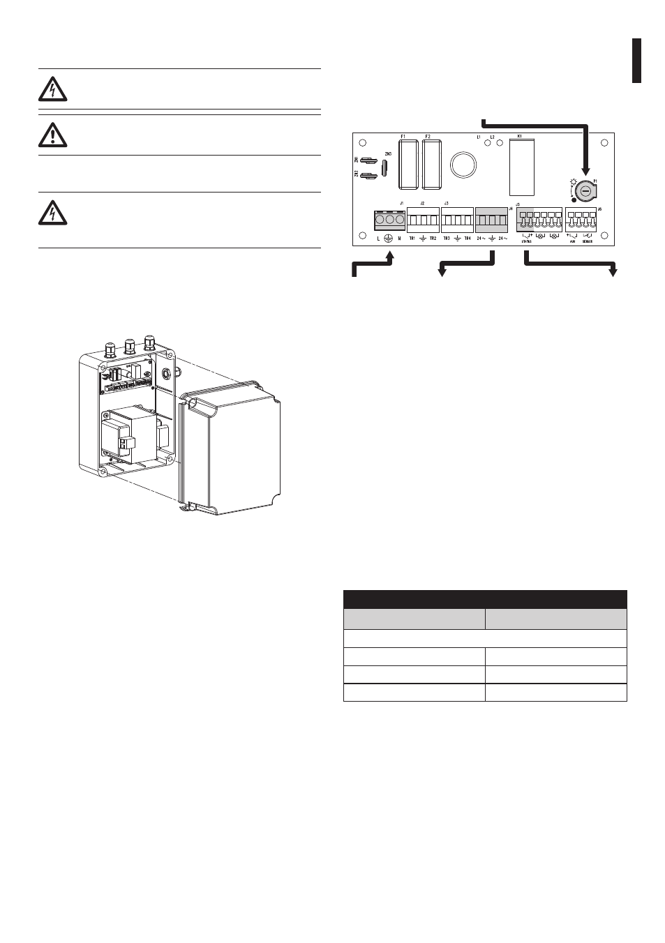
6.1.1 Connection of the board
Open the watertight box, taking care not to damage
the seals. Pass the power and control cables through
the appropriate cable glands.
Fig. 1
Locate the position of the trimmer, input and output
power supply terminals and Day/Night contacts on
the control board.
P1 - Sensitivity adjustment
trimmer
J1 - IN 230 Vac J4 - OUT 24Vac
J5 - Day/Night
status
Fig. 2
6.1.2 Connecting the dusk switch for the
IR illuminator
Connect the Day/Night (J5) output identified by
STATUS (+) to the alarm input (refer to the P&T
manual).
Connect the second Day/Night (J5) output identified
by STATUS to the alarms common terminal of the P&T.
6.1.3 Connection of the pan & tilt power
supply line
Connect the 24Vac power supply output (J4) to the
power supply connector of the pan & tilt. Use cables
with section of 1.5mm² (AWG 16).
Connect the power supply cables as described in the
table below.
CONNECTION OF THE POWER SUPPLy LINE
Colour
Terminals
Power supply 24Vac
Defined by the installer
~/24Vac
Defined by the installer
~/24Vac
Yellow/Green
GND/Earth
Tab. 1