Installation / connection – Kenwood KMM-257 User Manual
Page 18
16
R
L
REAR/SW
REMOTE CONT
STEERING WHEEL
REMOTE INPUT
MUTE
P. CONT
ANT CONT
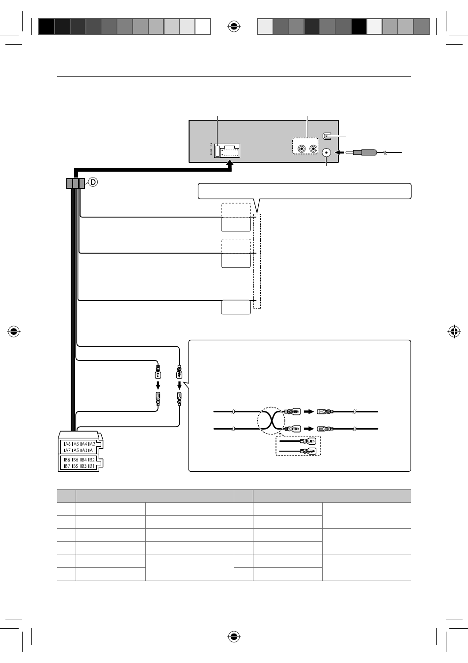
Wiring connection
Fuse (10 A)
Rear/subwoofer output
Antenna terminal
Rear ground terminal
If no connections are made, do not let the wire come out from the tab.
INSTALLATION / CONNECTION
Light blue/yellow
(Steering remote control wire)
To the steering wheel remote control adapter
Blue/White
(Power control wire/ Antenna control wire)
Brown
(Mute control wire)
To the power control terminal when using the
optional power amplifier, or to the antenna control
terminal in the vehicle.
To the terminal that is grounded when either
the telephone rings or during conversation. (To
connect the Kenwood navigation system, consult
your navigation manual.)
Yellow (A4)
Red (Ignition wire)
Red (A7)
Yellow (Battery wire)
ISO connectors
Connecting the ISO connectors on some VW/Audi or Opel (Vauxhall)
automobiles
You may need to modify the wiring of the supplied wiring harness as
illustrated below.
Unit
Vehicle
A7 (Red)
Ignition wire
(Red)
A4 (Yellow)
Default wiring
Battery wire
(Yellow)
Pin
Color and function
Pin
Color and function
A4 Yellow
Battery
B3 Gray
ª
Front speaker (right)
A5 Blue/White
Power control
B4 Gray/black
·
A7 Red
Ignition (ACC)
B5 White
ª
Front speaker (left)
A8 Black
Earth (ground) connection
B6 White/black
·
B1 Purple
ª
Rear speaker (right)
B7 Green
ª
Rear speaker (left)
B2 Purple/black
·
B8 Green/black
·
EN_KMM-357SD[EN]1.indd 16
EN_KMM-357SD[EN]1.indd 16
11/7/12 3:41:48 PM
11/7/12 3:41:48 PM