Agency listings and approvals, Product line information, Wiring diagrams – Notifier PIBV2A User Manual
Page 2
Page 2 of 2 — DN-1785:A1 • 1/12/10
NOTIFIER® and System Sensor® are registered trademarks of Honeywell
International Inc.
©2009 by Honeywell International Inc. All rights reserved. Unauthorized use
of this document is strictly prohibited.
This document is not intended to be used for installation purposes.
We try to keep our product information up-to-date and accurate.
We cannot cover all specific applications or anticipate all requirements.
All specifications are subject to change without notice.
For more information, contact Notifier. Phone: (203) 484-7161, FAX: (203) 484-7118.
www.notifier.com
Agency Listings and Approvals
The listings and approvals below apply to the PIBV2 or
PIBV2A supervisory switches. In some cases, certain modules
may not be listed by certain approval agencies, or listing may
be in process. Consult factory for latest listing status.
•
UL/ULC Listed: file S739.
•
ULC Listed: file CS169 (model PIBV2A).
•
CSFM approved: file 7770-1209:149, 7770-1653:118.
•
FM approved.
•
MEA approved: file 427-91-E, 167-93-E.
•
BSA approved: file 750-76-SA.
Product Line Information
PIBV2: Post Indicator/Butterfly Valve supervisory switch.
PIBV2A: ULC model, Post Indicator/Butterfly Valve supervi-
sory switch.
546-7000: Cover tamper switch kit.
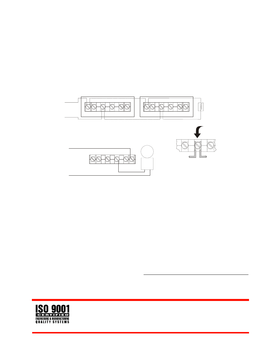
Wiring Diagrams
to nonsilenceable
initiating zone of
Listed FACP
end-of-line
resistor
supervisory switch
supervisory switch
TYPICAL FACP CONNECTION
COM
COM
B
B
COM
COM
B
B
COM
B
to power source
compatible with bell
local
bell
TYPICAL LOCAL BELL CONNECTION
BREAK WIRE as shown for
supervision of connection.
DO NOT allow stripped
wire leads to extend
beyond switch housing.
DO NOT loop wires.
1785w3a.wmf
1785w2a.wmf
1785w2a.wmf