Cone of vision, Installation and wiring, Maintenance – Notifier 30-2021E-24 User Manual
Page 2: Engineering specifications, Agency listings and approvals
Page 2 of 4 — DN-1253:B • 8/25/2010
Cone of Vision
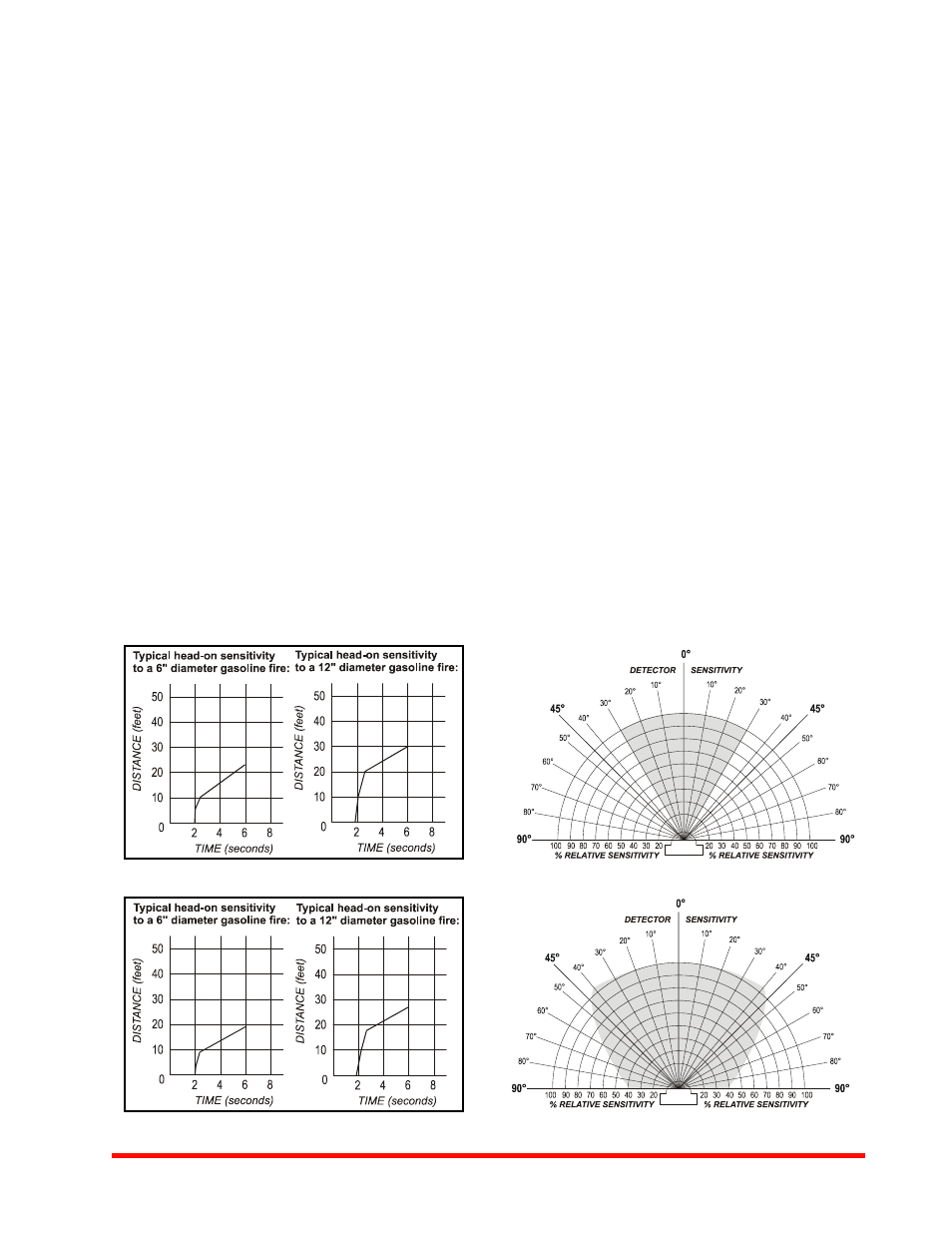
The Model 30-2021-24 has an 180° cone of vision. Relative
sensitivity is greatest at a viewing angle of 45° on either side of
the central axis. At angles greater than 45°, sensitivity
decreases, as illustrated in Figure 3. For the viewing pattern of
Model 30-2021E-24, with 60° cone of vision, see Figure 4.
Installation And Wiring
The Model 30-2021-24 and Model 30-2021E-24 are intended
for use in indoor applications. Connection to both models is via
color-coded wire leads with the following functions:
•
RED: +24 V operating power input.
•
BLACK: Common 24 V operating power input.
•
WHITE: ALARM relay – common.
•
BLUE: ALARM relay – normally closed contact.
•
ORANGE: ALARM relay – normally open contact.
The Model 30-2021-24 can be mounted on a standard 4"
(10.16 cm) junction box. The junction box should be mounted
securely to a supporting surface such as a wall, piping, etc.
See Figure 5 for 30-2021-24 mounting hole locations. Connect
the external wiring to the detector as illustrated in Figure 7 and
Figure 8
.
To install the Model 30-2021E-24, remove the front cover from
the detector and mount the detector on the junction box. See
Figure 6
for 30-2021E-24 mounting hole locations. Make the
electrical connections as shown in Figure 7 and Figure 8.
Place the cover back on the detector and mount it to any flat
surface.
A swivel mount is available for use with the Model 30-2021E to
facilitate installation and orientation and provide easy adjust-
ment for the viewing field of the detector — order part number
10-3995. This optional accessory meets the same NEC
requirements for use in hazardous areas as the detector.
Maintenance
To assure maximum detector sensitivity, keep the surface of
the sensor tube free from dirt or other contaminants at all
times. Periodically test the sensitivity of the detector using a
controlled flame or a UV test lamp such as the model W8066.
Engineering Specifications
The unit shall be an open area ultraviolet flame detector
designed to operate on 24 VDC.
It shall have encapsulated electronic circuitry and Form-C
alarm relay contacts. The unit shall have built-in alarm indica-
tion from the front of the detector. It shall respond to a 12-inch
(30.48 cm) diameter gasoline fire in six seconds when viewed
head-on from a distance of 30 feet (9.144 m). The detector
shall not respond to normal ambient light conditions such as
sunlight, incandescent, or fluorescent light.
The detector shall have a three-second time delay to spurious
responses. Model 30-2021-24 shall have a 180° cone of vision
with the greatest sensitivity at 45° on either side of the central
axis. Model 30-2021E-24 shall have a 60° cone of vision.
Explosion-proof units shall meet NEC Class I, Groups C and
D; Class II Groups E, F, and G; Class III.
Agency Listings and Approvals
Consult panel manuals for lists of compatible UL-Listed
devices. In some cases, certain modules or applications may
not be listed by certain approval agencies, or listing may be in
progress. Consult factory for latest listing status.
Figure 1 Model 30-2021-24 Detector Sensitivity
1253f1a.wmf
1253f1b.wmf
Figure 2 Model 30-2021E-24 Detector Sensitivity
1253f2a.wmf
1253f2b.wmf
Figure 3 Model 30-2021-24
1253fig3.wmf
Figure 4 Model 30-2021E-24
1253fig4.wmf