Sar 331 sa gds, Regulating the machine – Dake Model SAR 331 User Manual
Page 10
10
SAR 331 SA GDS
REGULATING
THE MACHINE
7.1 - Blade tension assembly
7
The ideal blade tension is obtained by turning the belt-tighten-
ing handwheel until the relative microswitch activates (B).
The position of the microswitch is established by an instru-
ment that measures the blade stretch. This regulation must not
be modified.
NB: it is advisable to loosen the blade tension when the saw is not
being used.
It is advisable to always use blades having the dimensions declared
in this manual.
B
7.3 - Vice
- The vice can be made to move rapidly towards the piece to be
cut by keeping the hand lever (C) raised and moving the vice
manually. Before using the handwheel to lock the material to
be cut, make sure that the hand lever is interlocked with the
rack.
- The vice group can be positioned to the right or left of the
blade. If positioning is not fully completed, the sawing ma-
chine can be permanently damaged by the lowering move-
ment of the frame.
- Always keep the vice guide and relative thread clean and
oiled.
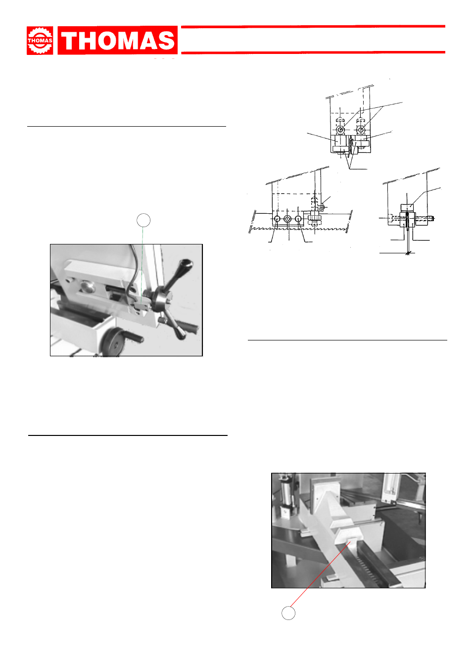
7.2 - Blade-guiding arms and plates
The blade is guided by plates that are regulated during the
testing phase according to the thickness of the blade. The mini-
mum clearance indicated in the figures should be maintained.
When the blade is to be replaced, make sure to always fit belts
with a 0.9 mm thickness because the blade-guiding plates have
been regulated for this thickness. If using toothed belts with
different thicknesses a new regulation must be carried out as
follows:
- Loosen the screw (1) and unscrew the grub screws (2), wid-
ening the space between the plates.
- Loosen the nuts (3) and the grub screws (4) and rotate the
pins (5 - 6) to widen the space between the bearings (7).
- Insert the new blade, then place the plate (8) against it. Tighten
the grub screws (2), leaving a 0.04 mm clearance to ensure
that the toothed belt slides well. After this, tighten the relative
nuts and the screw (1).
- Rotate the pins (5 - 6) until the bearings lean against the
blade, as indicated in the figure. Lock the grub screws (4) and
the nuts (3).
1
2
2
4
5
6
7
8
C
3
0,04