Summers Disk-Chisel User Manual
Page 33
HITCH-LOCKS
3/16/2009
9CC4012-2008.iam/
A
8X0223
1/4" FN
8K8067
8D8490
8X0000
1/4 X 3/4"
8X0110
3/4 X 1.25"
8X0318
3/4" FW
8D8500
8D8522
8T4000
8X0234
7/16" LNUT
8K1640
8X0044
7/16" X 3-1/2"
8X0402
8X0432
CLVS PIN
8S1120
8A1156
3/8 X 4-1/16 X 5"
8T4350
8X0402
8X0440
8S0340
1/2 X 4 X 5 1/4" SQ
8T4380
8X0303
1/2" LW
8X0240
1/2" N
8S1126
8X0021A
8S1124
8K8200
8X0203
3/8" FN
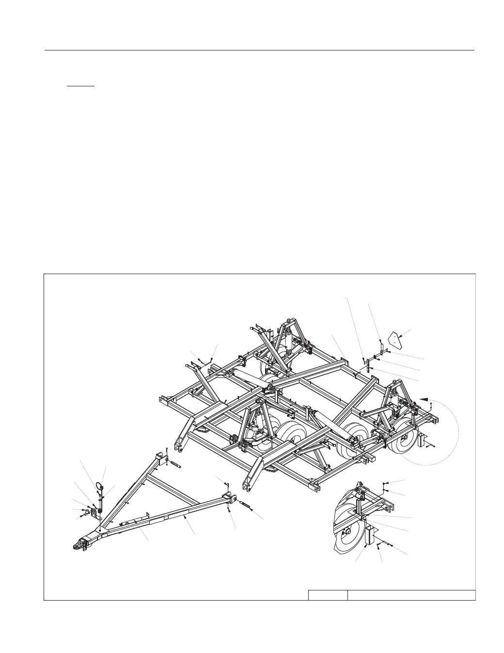
SECTION 2 – SET-UP OF CENTER SECTION 40’
2-21
14. Attach hitch to center with 1-1/2” x 10-5/8” pins.
NOTE: Center with 1-1/2” ID 10 GA fl at washers.
15. Install 7/16x3-1/2” retaining bolts through hitch pivot pins. Secure with lock nuts.
16. Attach hydraulic hose holder and tip holder with 3/4 x 1-1/4” bolt and fl at washer.
17. Attach hitch jack to jack spool.
18. Remove blocks from under center frame and allow wheel assemblies to support machine. Block
tires to prevent movement.
19. Add depth control cylinder locks and storage bases.
– Attach locks for rear cylinders by liftarm pivots located closest to center of machine.
– Locate lock for front center cylinder on front 4 x 4 tube.
20. Install SMV sign mounting bracket and sign at center of rear rank.