Summers Disk-Chisel User Manual
Page 25
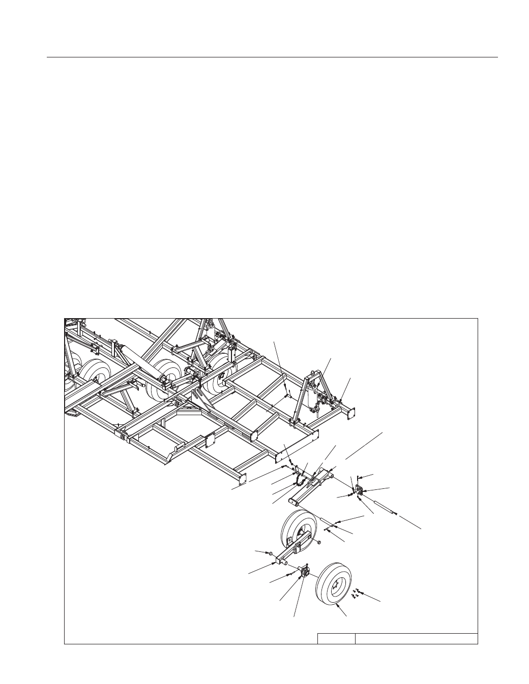
WING-TRANSPORT
3/13/2009
9CC3612-2008.iam/
8D9108
1/4 X 2" RP
8K9106
8K5515
3/4 X 4 X 6"
8T3640
8X0234
7/16" LNUT
8T4100
8X0044
7/16" X 3-1/2"
8X0260
3/4" N
8X0306
3/4" LW
8D0340
3/4 X 4 X 7-3/4"
8X0067
1/2-13NCX2-1/4"
8T3120
8L1110
8X0261
3/4" LN
8X0322
1/2" FW
8X0242
NY-LOCK 1/2" N
8T3620
8X0044
7/16" X 3-1/2"
8S3059
2.067" CAPLUG
8T4168
8X0072
1/2" X 3-3/4"
8K1100
8X0242
NY-LOCK 1/2" N
8R6914
8K7033
8T4140
8T1060
SECTION 2 – SET-UP OF 32’-36’ WINGS
2-13
– Insert 7/16 x 3-1/2” bolt in retaining bolt hole. Secure with lock nut.
5. Install walking tandem assembly to bottom of liftarm.
– The left hand wing uses a right hand assembly – 8T4168.
– The right hand wing uses a left hand assembly – 8T4166.
– Slide pivot pin (8T3620) through walking tandem assembly and liftarm.
– Insert 7/16 x 3-1/2” bolt in retaining bolt hole. Secure with lock nut.
6. Hang cylinders in appropriate location. Use pins and roll pins.
– Rod end of cylinder must point towards ground.
– Use 6 x 10” (8T1060) on left hand wing.
– Used 4-1/2 x 10” (8T1045) on right hand wing.
7. Install 8K1100 axle and hub assembly into each walking tandem. Apply good quality anti-seize to
axles before installation. Retain axle into receiver tube with 1/2 x 3-3/4” bolt and locknut.
8. Attach wheels onto hubs with 9/16” wheel bolts (torque required: 122 ft-lbs).