AMETEK 7250 Digital Stick User Manual
Page 6
6
Specifications
Indicated Level
up to one product reading
and one interface reading
316 Stainless Steel
Resolution
1
Repeatability
Linearity
Hysteresis
PVDF (Rigid)
Resolution
1
Repeatability
Linearity
Hysteresis
PVDF (Flexible)
Resolution
1
Repeatability
Linearity
Hysteresis
Lengths up to 288”
0.0001”
Equal to Resolution
+/- 0.01%
2
+/- 0.002%
3
Lengths up to 192”
0.0001”
Equal to Resolution
+/- 0.01%
2
+/- 0.002%
3
Lengths from 193” up to 840”
0.0001”
Equal to Resolution
+/- 0.01%
4
+/- 0.002%
3
Logic Levels
V
OH
2.7v (Leakage current is less than 1µA)
V
OL
0.4v (5mA load)
V
IH
2.1v
V
IL
0.9v
Cable
The cable will be a shielded
3 conductor 22AWG with a
PVC jacket (Belden 6501FE
or equivalent)
Red Power
White Data Signal
Black Common
Drain Cable shield,
Chassis ground on S.S. housing probes
Indicated Temperature
up to 5 temperature sensors
Resolution
Repeatability
Accuracy
0°C to +100°C
-40°C to -1°C & +101°C to +125°C
0.1°C
+/- 0.3°C
+/- 0.75°C
+/- 1.0°C
Data Update Time
1
Position data
Temperature data
0.100 seconds
0.800 seconds
Power Supply
Voltage
Current (@+5VDC)
+5 VDC, +/- 10 % typical (+3.7VDC Minimum)
10mA max. (8mA typical) plus
1.5mA max (1mA typical) per temperature sensor
Intrinsically Safe
Entity Parameters
V
max
7.93 V
I
max
280 mA
P
I
1.0 W
C
I
30.1 uF
L
I
0 µH
Operating Temperature: -40ºC to 70ºC (Consult Factory for Higher Temperatures)
Specifications are subject to change without notice. Patented.
1
protocol dependent
2
or +/- 0.015”, whichever is greater
3
or +/- 0.005”, whichever is greater
4
or +/- 0.039”, whichever is greater
725
X
X
X
XX
LLL
Fx
XXX
X
XX
Overall Length
Specify in whole 1”
increments. ie. 072 = 72”
Mounting Style
X = None
C = “C” Version
T = Tri-Clamp
B = Fixed Bottom
P = C.I.P. (3A)
H = Condulet
D = Dual XP
Extensions
E = Fixed Bottom
F = Fixed Top
Connector Style
M = Mini
R = 1/2” NPT Right Angle
D = 3/4” NPT Dual
S = 3/4” NPT Single (Steel)
1/2” NPT Single (PVDF)
B = Fixed Bottom
# of Temp Points
R1 = 1 Sensor
R5 = 5 Sensors
T1 = 1 Sensor
7250 Series
HR Digital Stik
Output Protocol
2 = 25 Level Readings
5 = 10 Level Readings
Span
Max Level
# of Floats
F1 = 1 Floats
F2 = 2 Floats
Special Mounting
XX = None
For B Mounting Style
S0 = Std., Stainless Steel
S1 = Mast Mount, Stainless Steel
S2 = M.M. w/ Cordgrip, Stainless
Steel
Consult factory for other options.
For T Mounting Style
20 = 2”
25 = 2.5”
30 = 3”
40 = 4”
Style/Material
X = 316 Stainless Steel
V = PVDF
S = Sanitary
F = Food Grade
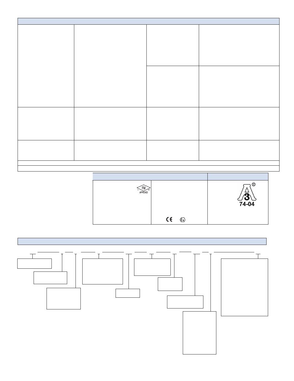
7250 Series Part Numbering
7250 Series Specifications
7250 Series Part Numbering Sequence
FM
-40° =< Tamb =< 70° C
Class I, II, III, Div. 1
Groups C, D, E, F, G, T4
Class I, Div. 2
Groups A, B, C, D, T4
Class I, Zone 0, AEx ia IIB T4
ATEX
AEx/Ex ia llB T4
NEMKO 05 ATEX 1219X
IECEx FMG 12.0008X
Issued Date: 06/29/12
IEC 60079-0:2011
IEC 60079-11:2011
Hazardous Areas Approvals
Sanitary Approvals
IEC 60079-26:2006
INMETRO IEE 12.0046X
(See PVDF installation note)
0344
II 1G