Caution – AMETEK 7250 Digital Stick User Manual
Page 4
4
Calculation of Checksum:
All the ASCII characters (from and including
the start character to and including the comma
(‘,’) after the final temperature digit) in the data
string are added together. From this number, the
least significant byte is used for the checksum
value and is transmitted in its equivalent ASCII
characters. Note that capital letters MUST be
used for the upper hex values (i.e. ‘A’, ‘B’, ‘C’, ‘D’,
‘E’, ‘F’).
For example:
If the checksum value was 0xA5 (hex); An ASCII
‘A’ and a ‘5’ characters would be transmitted
to indicate the checksum value (i.e. 0x41 and
0x35.....the ASCII characters for ‘A’ and ‘5’).
Data Transmission Example
The following example represents the data
transmitted from a 7255 HR Digital Stik (i.e. 10
product levels) which has a full transmission data
string length of 134 bytes. Bytes 0 – 130 are
used to compute the checksum:
NOTE: The Level values used in the following
chart may not be representative of a real life
application. The data provided is for example
purposes only.
Byte #s
ASCII Chr String
Level Name
0-1
<,
Start Character
2-10
123.4567,
Product 1
11-19
456.7890,
Product 2
20-28
654.3212,
Product 3
29-37
987.6543,
Product 4
38-46
124.5789,
Product 5
47-55
234.5678,
Product 6
56-64
267.4310,
Product 7
65-73
478.2354,
Product 8
74-82
752.6143,
Product 9
83-91
891.4578,
Product 10
92-100
002.5389,
Interface 1
101-106
+22.1,
Temperature 1
107-112
+22.3,
Temperature 2
113-118
+22.5,
Temperature 3
119-124
+22.3,
Temperature 4
125-130
+22.1,
Temperature 5
131-132
CC
2-digit ASCII Checksum
133
Carriage Return
NOTE: To determine the actual location of a
temperature sensor, refer to the Thermometer
Spacing tables on Drawing D0246600, sheet 2 of
2, included on page 9 of this manual.
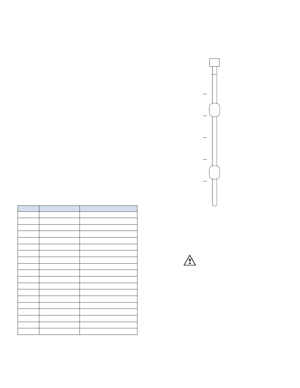
Fig. 2 Temperature Sensor Location and Spacing
for the 7250X Series
Installation of PVDF Probe
CAUTION
NOTE: The surface of the isolating material
(PVDF) exceeds the limit of 4cm
2
as specified in
EN60079-26, and the probability of electrostatic
charging needs to be considered for use in
category 1 (Zone 0).
Part of the equipment enclosure is constructed
of non-metallic material; to prevent the risk
of electrostatic sparking, the non-metallic
enclosure material should be cleaned only with a
damp cloth.
Temperature 5
Temperature 4
Temperature 3
Temperature 2
Temperature 1
Head of Probe
Product Float
Interface Float
Foot of Probe