Catalog numbering system, Pilot operation, Additional options x none m manual push button – AMETEK 1500 Induction Style Relay User Manual
Page 4
4
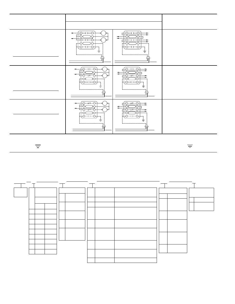
INDUCTION RELAY
CONTACT
ARRANGEMENT
WIRING DIAGRAM AND OPERATION
DIRECT OPERATION
TYPICAL
APPLICATIONS
Same as 1500-D Relay above
except that additional Normally
Closed contact is provided to permit
simultaneous operation of second
pump. Extra contact can also be
used for signal purposes if desired.
Pump Up or Pump Down Control for
same applications listed above for
B/W 1500-C and 1500-D Relays. It
is also suitable for use in controlling
hydropneumatic tanks and motor-
ized valve installations.
1500-H Relay
Two Electrode Wiring
Contact Arrangement
Normally Normally Holding
Open Closed Circuit
0 2 1
1500-G Relay
Two Electrode Wiring
Contact Arrangement
Normally Normally Holding
Open Closed Circuit
1 1 1
PILOT OPERATION
CAUTION: Electrodes are terminals of live electrical circuits and must be installed
to prevent accidental contact by personnel. Control power must be disconnected before servicing.
A GOOD DEPENDABLE GROUND RETURN CONNECTION TO THE LIQUID IS REQUIRED.
Same as 1500-C Relay above
except that additional Normally
Open contact is provided to permit
simultaneous operation of second
pump. Extra contact can also be
used for signal purposes if desired.
1500-F Relay
Two Electrode Wiring
Contact Arrangement
Normally Normally Holding
Open Closed Circuit
2 0 1
1
3
5
7
9
2
4
6
8
10
A.C.
LINE
TO ISOLATED
LOAD CIRCUIT
ELECTRODE
HOLDER
ELECTRODE
LOAD CIRCUIT A & B CLOSED ABOVE THIS LEVEL
LOAD CIRCUIT A & B OPEN BELOW THIS LEVEL
LINE
VOLTAGE
VOLTAGE
SECONDARY
A.C.
LINE
LOADS A & B DE-ENERGIZED BELOW THIS LEVEL
LOADS A & B ENERGIZED ABOVE THIS LEVEL
1
7
GROUND
9
5
3
VOLTAGE
8
10
SECONDARY
VOLTAGE
LINE
6
4
2
ELECTRODE
HOLDER
ELECTRODE
LOAD B
LOAD A
TO ISOLATED
LOAD CIRCUIT
B
A
GROUND
1
3
5
7
9
2
4
6
8
10
A.C.
LINE
TO ISOLATED
LOAD CIRCUIT
ELECTRODE
HOLDER
ELECTRODE
LOAD CIRCUIT A OPEN ABOVE THIS LEVEL - B CLOSED
LOAD CIRCUIT A CLOSED BELOW THIS LEVEL - B OPEN
LINE
VOLTAGE
VOLTAGE
SECONDARY
A.C.
LINE
LOADS A ENERGIZED BELOW THIS LEVEL - B DE-ENERGIZED
LOAD A DE-ENERGIZED ABOVE THIS LEVEL - B ENERGIZED
1
7
GROUND
9
5
3
VOLTAGE
8
10
SECONDARY
VOLTAGE
LINE
6
4
2
ELECTRODE
HOLDER
ELECTRODE
LOAD A
LOAD B
TO ISOLATED
LOAD CIRCUIT
A
B
GROUND
1
3
5
7
9
2
4
6
8
10
A.C.
LINE
TO ISOLATED
LOAD CIRCUIT
ELECTRODE
HOLDER
ELECTRODE
LOAD CIRCUIT A & B OPEN ABOVE THIS LEVEL
LOAD CIRCUIT A & B CLOSE BELOW THIS LEVEL
LINE
VOLTAGE
VOLTAGE
SECONDARY
A.C.
LINE
LOADS A & B ENERGIZED BELOW THIS LEVEL
LOADS A & B DE-ENERGIZED ABOVE THIS LEVEL
1
7
GROUND
9
5
3
VOLTAGE
8
10
SECONDARY
VOLTAGE
LINE
6
4
2
ELECTRODE
HOLDER
ELECTRODE
LOAD B
LOAD A
TO ISOLATED
LOAD CIRCUIT
B
A
GROUND
Catalog Numbering System
All contacts rated at:
25 Amp Resistive at 120, 240, or 480 VAC
1 HP Single Phase at 120 or 240 VAC
Heavy Duty Pilot 120 to 600 VAC
2 Amp Resistive at 120 VDC
10 Amp Resistive at 48 VDC
1500
A
L1
S7
Contact
Arrangements
Normally
Open
Closed
A
1
0
B
0
1
C
2
0
D
1
1
E
0
2
F
3
0
G
2
1
H
1
2
J
0
3
Catalog
Section
Line Voltage
L1 110-120 Volts
50/60 HZ
L2 208-240 Volts
50/60 HZ
L3 440-480 Volts
50/60 HZ
L4 550-600 Volts
50/60 HZ
L5 Dual Voltage
120/240 Volts
50/60 HZ
Secondary
Coil Voltage
Typical Liquids
S1
12 Volts A.C.
Metallic circuits
S2
24 Volts A.C
Metallic circuits
S3
40 Volts A.C.
Acid or caustic solutions: Milk;
Brine and salt solutions; Plating
solutions; Buttermilk; Soups
S4
90 Volts A.C
Weak acid or caustic solutions:
Beer; Baby foods; Fruit juices
S7
220 Volts A.C.
Sewage; Most water-except very
soft; Pottery slip; Water soluble oil
solutions; Starch solutions
S8
360 Volts A.C.
Very soft water; Sugar syrup
S9
480 Volts A.C.
Steam condensate; Strong alcohol
solutions
S11 800 Volts A.C.
Demineralized or distilled water
OC
Enclosure Type
OC
Open Chassis
N1
NEMA 1
General
Purpose
N4
NEMA 4
Weather Proof
N4X NEMA 4X
Corrosion
Resistant
N7
NEMA 7
Classifi ed
Location
N12 NEMA 12
Oil Tight
X
Additional
Options
X None
M Manual
Push Button