Installation instructions – AMETEK 1500 Induction Style Relay User Manual
Page 2
2
Installation Instructions
Relay: Install relay in level upright position. Connect wires
from AC supply to terminals #3 and #4 on relay. Make sure
power is of same rated voltage and frequency as shown
for connection to primary coil on relay data plate. Relays
draw 9 volt amperes.
Electrodes: Install electrodes in tank or well by
suspending them vertically from an electrode holder or
some other suspending means. One electrode should be
set at desired start level and one at desired stop level. For
sewage or surface drainage sumps, make sure electrodes
are hung far enough apart so that foreign matter fl oating
on water cannot foul electrodes. Size 18 or larger Type TW
or THW wire is recommended for connection to the relay.
CAUTION - Although the electrodes are connected
to a low energy secondary coil output which has
inherently low current, there may be up to 800 volts
between the electrodes or from an electrode to
ground. (See Secondary Coil Table.) Thus wiring and
electrodes should be installed to protect personnel
from accidental contact.
Ground: A system ground return circuit is required from the
indicated relay terminal to the liquid in order to complete
the secondary circuit of relay. Conduit should not be
used. Instead, connection should be made directly to
uninsulated metal tank, or to metal pipe connected to tank
below normal low liquid level. In wells, connect ground
to pump or metallic water pipe. For concrete, wood, or
insulated tanks, use an extra common electrode extending
slightly below the longest operating electrode.
Secondary Coil: Because the secondary voltage on all B/
W relays is an induced voltage generated within the relay
itself, the secondary coil should never be connected to any
source of power. Voltage of the secondary coil installed on
a given relay is determined by conductivity of liquid to be
controlled.
Load Connections: B/W relays are two-wire control
devices having load contacts rated at 1 hp., single-phase,
115 or 230 volts AC or standard duty pilot rating up to 600
volts AC. In operation, load contacts act as a switch to
open or close a circuit. Connecting them to an external
load does not introduce a source of alternating current into
the circuit.
Accordingly, in making connections for direct operation of
single-phase loads within rated capacity of relay, power
connections must be made as shown in relay wiring
diagram.
To operate higher rated single-phase loads or three-
phase loads, a magnetic starter must be used. In making
connections to motor starter, follow directions given on
the starter wiring diagram for connecting two-wire control
devices.
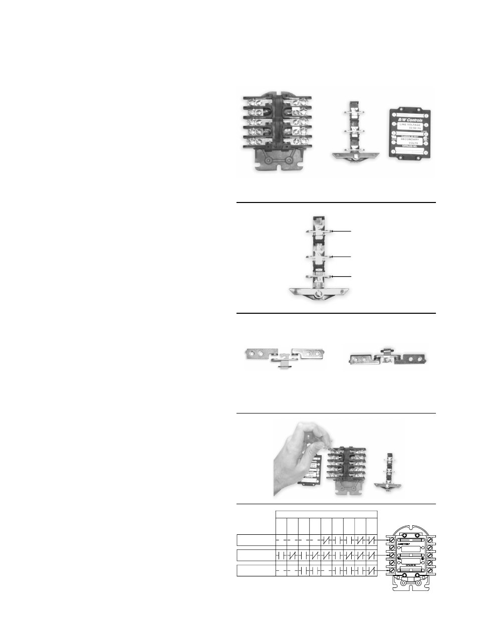
Field Replaceable and Convertible Contacts
The Series 1500 Induction Relay provides circuit versatility by offering
a contact kit that allows fi eld conversions from N.O. to N.C. or N.C.
to N.O. contact arrangements. This option also allows you to add or
replace contacts (up to 3 per relay) as required for expansion of your
liquid level control needs.
Remove cover plate and armature
N.O. Contact
N.C. Contact
For a N.O. contact, install the
stationary contacts facing toward
the bottom of the relay (toward the
armature).
For a N.C. contact, install the
stationary contacts facing in
toward the top of the relay (away
from the armature).
Contact Kit Part No. 15-000001
R
1
2
3
4
5
6
7
8
9
10
R
Clawson, Michigan 48017 U.S.A.
B/W CONTROLS
LINE VOLTAGE
50/60 Hz
SECONDARY
VOLTS
1500-
CONTACT ARRANGEMENT CODE
A B C D E F G H J
1 N.O.
1 N.C.
2 N.O.
1 N.O.
1 N.C.
2 N.C.
2 N.O.
1 N.C.
1 N.O.
2 N.C.
3 N.C.
3 N.O.
TOP CONTACT
TERMINALS 1 & 2
MIDDLE CONTACT
TERMINALS 5 & 6
BOTTOM CONTACT
TERMINALS 9 & 10
N.O.
N.O.
N.C.
For a N.O. contact,
install the moveable
contact in the
armature assembly
facing toward the top
of the relay. (away
from the armature)
For a N.C. contact,
install the moveable
contact in the
armature assembly
facing toward
the bottom of the
relay. (toward the
armature).