AMETEK 955S Smart Brik LDT User Manual
Page 7
7
1080 N. Crooks Road • Clawson, MI 48017 • 800.635.0289 • 248.435.0700 • Fax 248.435.8120 • www.AMETEKAPT.com
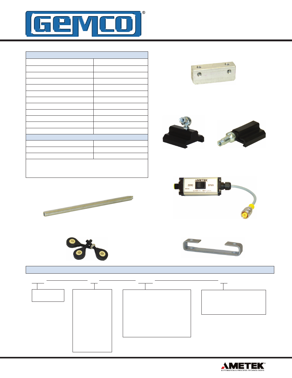
Accessories
Item
Part Number
Slide Magnet
SD0521800
Slide Magnet Side Adapter
SD0521801
Float Magnet
SD0522100
Mounting Foot
SD0522000
6 Ft. Cable
949001L6
12 Ft. Cable
949001L12
6 Ft. Cable, Right Angle Connector
949002L6
12 Ft. Cable, Right Angle Connector 949002L12
Control Arm
955ARMXX (X = Inches)
In-Line Programming Unit
955-1409
Rod Ends
04-570252
FM Accessories
6 Ft. Straight Cable
949024L6
12 Ft. Straight Cable
949024L12
Connector Lock
04-521570
NOTE: FM approved cordset and connector lock must be used and
installed per drawing E0241100 when installing the 955S in Class I
Div II, Group A, B, C, D applications.
Part Numbering
Control Arm P/N 955ARMXX
In-Line Programming Unit P/N 955-1409
Slide Magnet
P/N SD0521800
Rod Ends P/N 04-570252
Float Magnet P/N SD0522100
Slide Magnet
Side Adapter P/N
SD0521801
Mounting Foot P/N SD0522000
955S
XX
XXXX
Stroke Length
Insert stroke length to 0.1 inch. Enter
as a four-place number. Example: 12.0”
stroke is entered as 0120.
OR
Insert stroke length in millimeters to
1mm. Enter as a four-place number
followed by”M”. Example: 305mm stroke
is entered as 0305M.
955S
Smart BRIK
Output
V0 = 0 to 10 VDC
V1 = 10 to 0 VDC
V2 = -10 to 10 VDC
V3 = 10 to -10 VDC
V4 = 0 to 5 VDC
V5 = 5 to 0 VD
V6 = -5 to 5 VDC
V7 = 5 to -5 VDC
C2 = 20 to 4mA
C4 = 4 to 20mA
Options
Leave blank for no options.
E = Wet environment. Electronics
sealed to IP 68 Rating.