Connecting the breakout panel, Front view rear view, Champ connector and the breakout panel’s – ADTRAN 4200659L1 User Manual
Page 36: Champ connector (see figure 2-2), Figure 2-2. the breakout panel, Cable 1 cable 2
Chapter 2. Installation and Operation
2-6
MX2800 User Manual
61200659L1-1
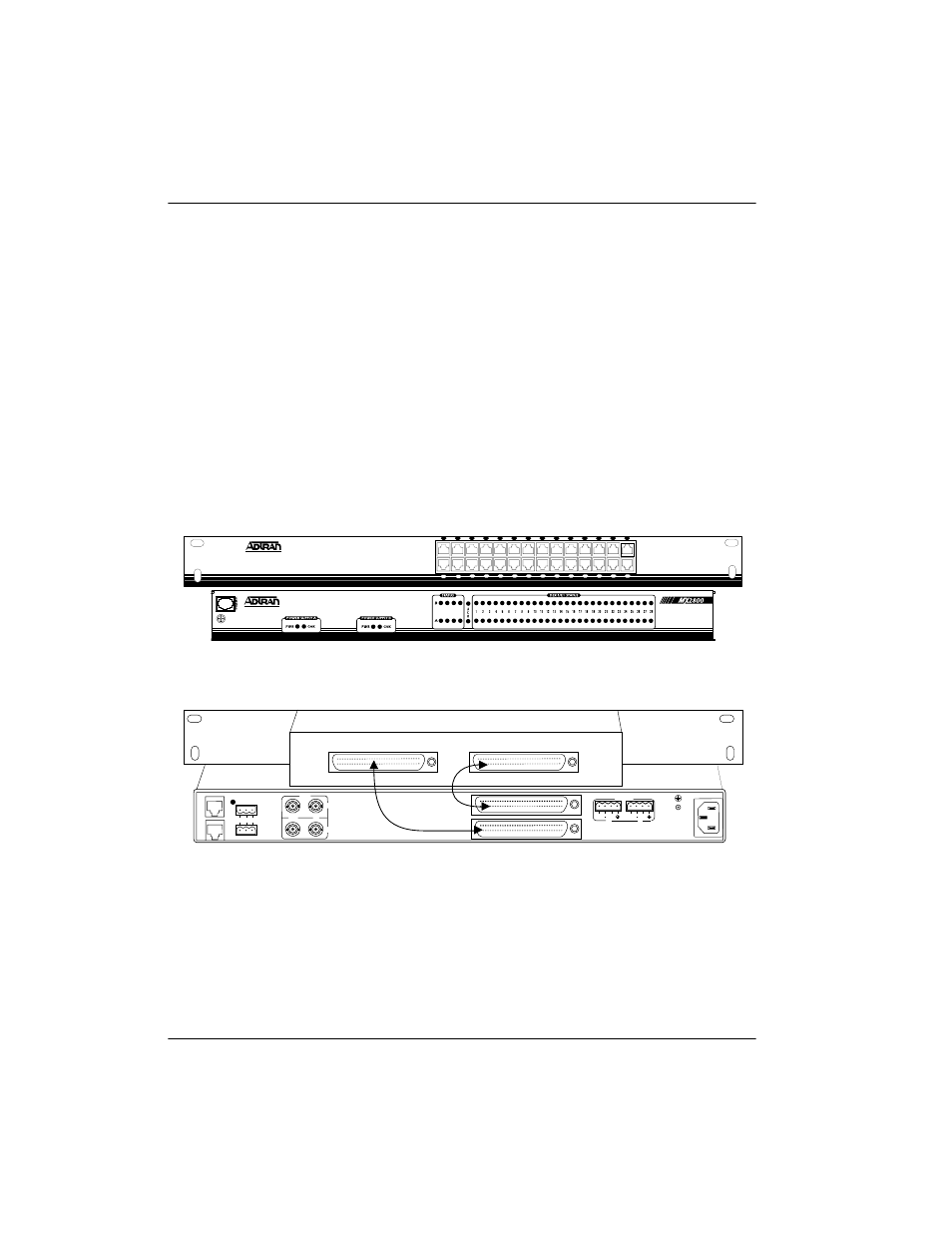
Connecting the Breakout Panel
The optional breakout panel (P/N 1200291L1) connects to the
MX2800 STS-1 via the
IN
and
OUT
Champ connectors located on
the back of the unit, and provides 28 RJ connectors for the
individual T1s/E1s. Shipment includes two six-foot, 64-pin to
64-pin Amp cables which allow direct cabling to the
MX2800 STS-1. Connect the breakout panel’s
IN
Champ connector
to the MX2800 STS-1’s
IN
Champ connector and the breakout
panel’s
OUT
Champ connector to the MX2800 STS-1’s
OUT
Champ
connector (see Figure 2-2).
Figure 2-2. The Breakout Panel
L
A
N
M
O
D
E
M
CRITICAL
NO COM NC
NONCRITICAL
IN
OUT
A
B
DSX-1/E1
(OUT)
DSX-1/E1
(IN)
USE COPPER
CONDUCTORS ONLY!
PWR
FAIL
RET
RET
PWR
FAIL
A
B
DC POWER
115VAC 50/60HZ
0.8a
IN
OUT
N E T
1
3
5
7
9
11
13
15
17
19
21
23
25
27
2
4
6
8
10
12
14
16
18
20
22
24
26
28
N
E
T
A
L
M
P
R
F
A
C
T
Front View
Rear View
Cable 1
Cable 2