0 disassembly of the actuator unit from the valve, 1 disassembly of the actuator unit, 0 disassembly of the actuator unit – ARI Armaturen DP34 EN User Manual
Page 18: From the valve
Page 18
0040504000 1210
Operating and installation instructions
Pneumatic actuators - DP32 / DP33 / DP34
7.0 Disassembly of the actuator unit from the valve
The following points should be taken into account basides the general principles governing
installation work:
To proceed with the disassembly of the actuator unit from the valve, the following
must be observed:
- Drive the actuator with control pressure into the middle position.
- DP32, DP33:
Unscrew set screw and coupling with thread bush from the securing flange.
DP34:
Loosen cylinder screws.
Remove the lock washer, securing flange and thread bush from the actuator connection.
- Loosen the hexagon nuts and remove the actuator from the valve.
7.1 Disassembly of the actuator unit
- Unscrew coupling flange and locking nur from the actuator stem.
- Reduce the control pressure to „0“ and separate the control pressure connection line from
the compressed air.
- Loosen the screws (pos. 21) of the actuator unit and remove the diaphragm covering (pos.
18).
ATTENTION !
- Due to safety reasons, the system must be driven down prior to disassembly of
the actuator unit (in a pressureless state!).
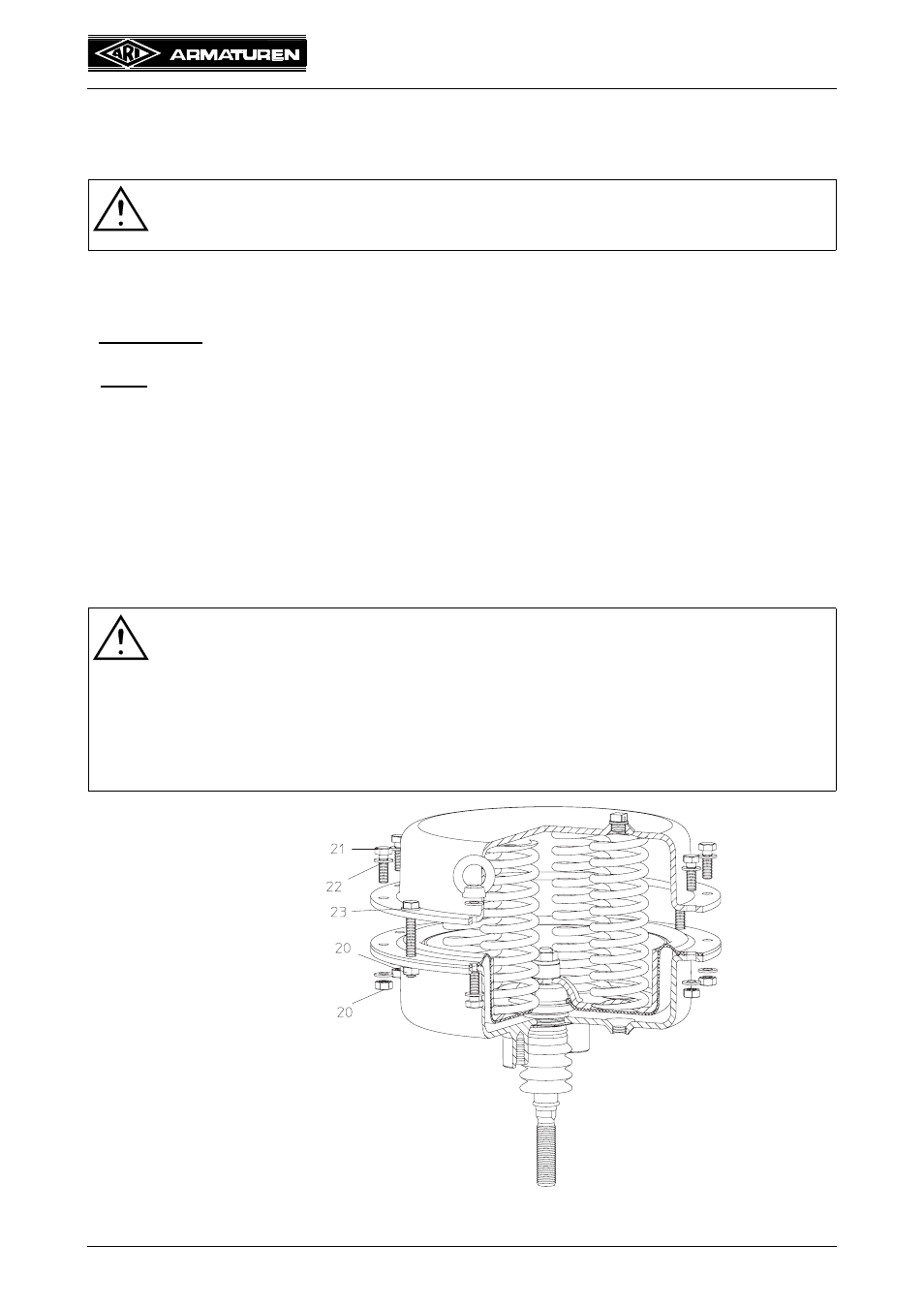
ATTENTION !
- For operations with increased initial spring tension (see Fig. 20), additional
screws have been provided for. For the sizes DP32 and DP33, there are an
additional two screws and for DP34, there are four longer screws (23) provided.
As the last step, the screws are to be loosened equally, in order to disassemble
the initial spring tension.
- The procedure must be followed according to this sequence, or else there
is a risk of INJURY.
Fig. 20